Basic installation – tekmar 367 Zone Control User Manual
Page 6
6
UnOccupied Temperature
When the 367 is in UnOccupied mode, the
UnOccupied light is turned on and the
UnOccupied dial is used to set the desired temperature within the UnOccupied zones.
Note If the RTU dial for an UnOccupied zone is set below the
UnOccupied dial, the 367
continues to use the RTU dial as the desired temperature within that zone.
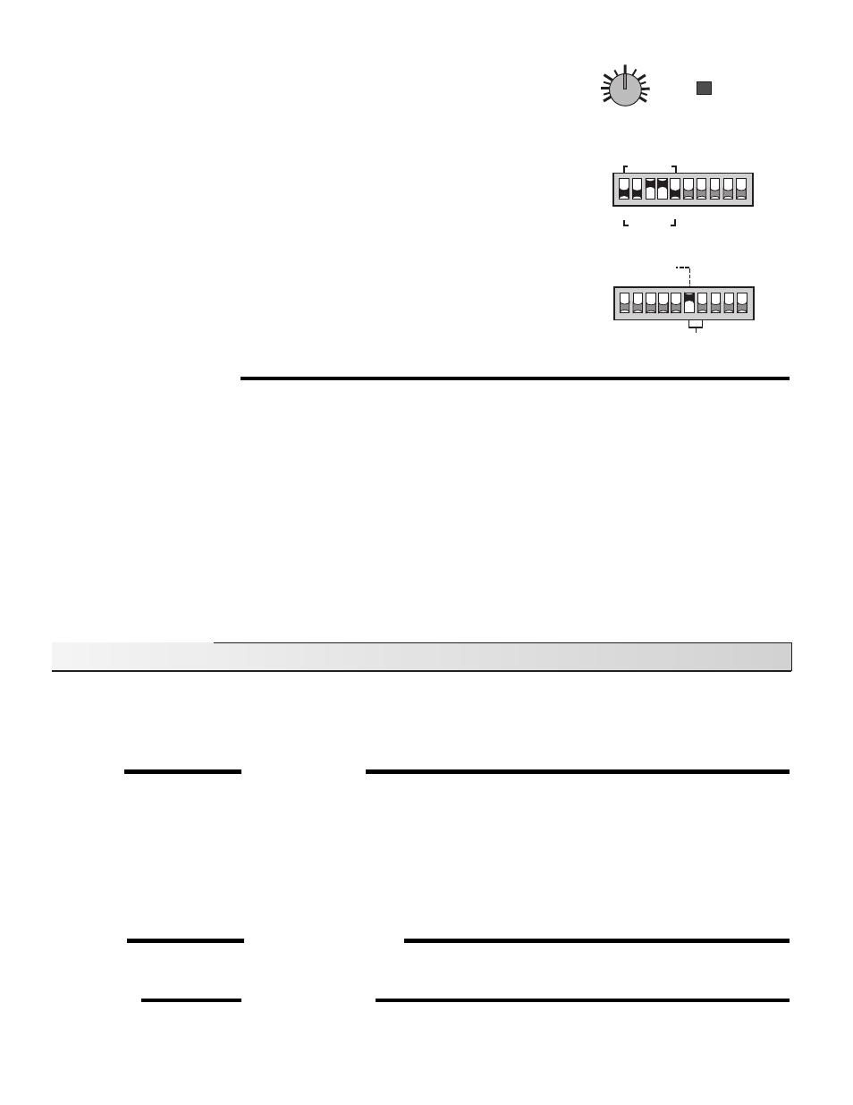
Individual Zone Selection
The DIP switch on the 367 is used to select which zones are switched into UnOccupied
mode. If the DIP switch for a specific zone is set to
Occ / UnOcc, that zone is switched
into UnOccupied mode whenever the 367 receives an UnOccupied signal. If the DIP
switch for a specific zone is set to
Occ. only, the zone remains in the Occupied mode at
all times.
Optimum Start / Stop
The Optimum Start / Stop feature is enabled when the DIP switch is set to
Optimum Start.
The 367 turns on the
Optimum Start / Stop light each time the first zone enters its delay
or recovery period. Either the tekmar Timer 031 or the built in 24 hr. Timer on the 367 can
be used with the Optimum Start / Stop feature. The tekmar Timer 031 has a DIP switch
which must be set to
Optimum Start / Stop in order to synchronize the timer with the 367
Optimum Start / Stop function. For more information on the Timer 031 consult the Data
Brochure D 031.
SYSTEM PUMP OPERATION
The
System Pump light is turned on every time the relay contact between terminals System Pmp — System Pmp (1 & 2) is closed. During
heating operation, the system pump operates whenever any zone requires heat. If thermal motor zone valves are used, the system pump
is held off for the first three minutes of the zone cycle in order to give the zone valve sufficient time to open. The system pump may also
operate for an additional purge period once the zone relays are turned off.
Pump / Valve Exercising
The zone valves, zone pumps and system pump are exercised to help prevent corrosion from building up and subsequently jamming
the equipment. Every three days the 367 runs through the following exercising procedure.
Exercising Procedure
The 367 first exercises the zone valves or pumps. If a zone valve or zone pump has not been operated in the past 3 days, the 367
turns on the zone relay for 10 seconds.
Note The zone relay exercising time is increased to 3 minutes if the DIP switch is set to
Thermal Motor.
After the zone valves or pumps have been exercised, the 367 exercises the system pump. If the system pump has not operated
in the past 3 days, the 367 turns on the
System Pmp relay for 10 seconds.
Once the exercising procedure is complete, the 367 returns to its normal operating sequence.
Basic Installation
Caution
Improper installation and operation of this control could result in damage to the equipment and possibly even personal injury.
It is your responsibility to ensure that this control is safely installed according to all applicable codes and standards. This
electronic control is not intended for use as a primary limit control. Other controls that are intended and certified as safety
limits must be placed into the control circuit.
STEP ONE
GETTING READY
Check the contents of this package. If any of the contents listed are missing or damaged, please contact your wholesaler or tekmar sales
representative for assistance.
Type 367 includes:
• One Zone Control 367
• Data Brochures D 367, D 001
• Application Brochures A 367
Other information available:
• Essays
Note Carefully read the details of the Sequence of Operation sections in all applicable brochures to ensure that you have chosen the
proper control for your application.
STEP TWO
MOUNTING THE BASE
Remove the control from its base by pressing down on the release clip in the wiring chamber and sliding the control upwards. The base
is then mounted in accordance with the instructions in the Data Brochure D 001.
STEP THREE
ROUGH-IN WIRING
All electrical wiring terminates in the control base wiring chamber. The base has standard 7/8" (22 mm) knockouts which accept common
wiring hardware and conduit fittings. Before removing the knockouts, check the wiring diagram and select those sections of the chamber
with common voltages. Do not allow the wiring to cross between sections as the wires will interfere with safety dividers which should
Off
Optimum Start
UnOccupied
70
°
F
(21
°
C)
40
(4)
100
(38)
UnOccupied
Zone
Occ/UnOcc
1,2
4
3
Occ. only
5
6