Settings, Step two, Step three – tekmar 155 Difference Setpoint Control User Manual
Page 2: Step four, Programming
2
Step Two
Mounting
The control is mounted in accordance with the instructions in the Data Brochure D 001.
Step Three
Rough-in wiring
All electrical wiring terminates in the two wiring chambers at the bottom front of the control. If the control is to be mounted on
an electrical box, the wiring can be roughed-in at the electrical box prior to installation of the control (see Brochure D 001).
Standard 18 AWG solid wire is recommended for all low voltage wiring to this control.
Power should not be applied to any of the wires during the rough-in wiring stage.
• Install the Source Sensor 085 and Storage Sensor 071 according to the instructions in Data Brochure D 085 and D 070, and run
the wiring back to the control. Do not connect the wires to the terminals yet.
• EITHER: Install a 24 V (ac) Class 2 transformer with a minimum 5 VA rating and run the wiring from the transformer to the control.
A Class 2 transformer must be used. Do not connect either of the transformer secondary wires to ground.
OR: Install a 24 V (dc) source and run the wiring back to the control.
• Run wiring back to the control from the devices connected to Relay 1 and Relay 2.
Step Four
Testing and connecting the wiring
Caution These tests are to be performed using standard testing practices and procedures and should only be carried out by properly
trained and experienced persons. A good quality electrical test meter, capable of reading from at least 0 — 200 Volts, and
at least 0 — 2,000,000 Ohms, is essential to properly test this control. At no time should voltages in excess of 27 V (ac or
dc) be measured at any of the wires connected to the control.
Test the sensors
• This test must be performed
before power is applied to the control and before the sensors are connected to the terminal strip.
Test the sensors according to the instructions in the enclosed Data Brochure D 085 and D 070.
Test the power supply
• Ensure exposed wires are not grounded or in contact with other wires, then turn on the power supply. If a 24 V (ac) transformer
is used, make sure the voltmeter is set to AC. With the voltmeter leads connected to the secondary side of the transformer, you
should measure between 21 and 27 V (ac). If a DC power supply is used, make sure the voltmeter is set to DC. Connect the positive
lead from the voltmeter to the positive terminal on the DC source and the negative lead from the voltmeter to the negative terminal
on the DC source. The voltmeter should measure between 21 and 27 V (dc).
• Turn off the power and complete the electrical connections to the terminal strip of the control.
Power and output connections
The installer should test to confirm that no voltage is present at any of the wires.
• EITHER: Connect the 24 V (ac) power supply to terminals
Power C- and R+ (1 and 2)
OR: Connect the negative (-) lead from the 24 V (dc) source to the Power C- terminal
Connect the positive (+) lead from the 24 V (dc) source to the Power R+ terminal
Note: The control will not operate if the DC leads are reversed.
• Connect the Relay 1 controlled device to terminals
Relay1 (3 and 4)
• Connect the Relay 2 controlled device to terminals
Relay 2 (5 and 6)
Sensor connections — Caution, voltage is never applied to these terminals
• Connect the Source Sensor 085 to terminals
Com Sen and Src Sen (7 and 8)
• Connect the Storage Sensor 071 to terminals
Com Sen and Stor Sen (7 and 9)
Do not apply
power here
24 V
power
supply
Relay 1 closes to
transfer heat
from the source
to the storage
Relay 2 closes to
satisfy drainback
or draindown
requirements
1
C-
2
R+
3
4
10A
10A
Relay 1
Relay 2
5
6
7
Com
Sen
Src
Sen
Stor
Sen
8
9
Source
Sensor
085
Storage
Sensor
071
Power
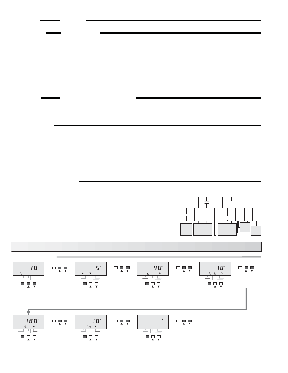
Settings
Note: The control automatically
exits programming when
the buttons are left alone
for 20 seconds.
Use the arrow
keys to set the
“ΔT Differential”.
Press and Release
the “Item” button to
change the display to
the “ΔT Differential”.
Press and Release
the “Item” button to
change the display to
the “Minimum Source
Setpoint”.
Use the arrow
keys to set the
“Minimum
Source
Setpoint”.
Press and Release
the “Item” button to
change the display to
the “Minimum Source
Differential”.
Use the arrow
keys to set the
“Minimum Source
Differential”.
Press and Release
the “Item” button to
change the display to
“°F” or “°C”.
Use the arrow
keys to switch
between “°F”
and “°C”.
Use the arrow
keys to set the
“ΔT setpoint”.
PROGRAMMING
Press and Release
all three buttons at the
same time to begin
programming. The first
item displayed is the
“ΔT setpoint”.
Press and Release
the “Item” button to
change the display to
the “Maximum Storage
Setpoint”.
Use the arrow
keys to set the
“Maximum
Storage
Setpoint”.
Press and Release
the “Item” button to
change the display to
the “Maximum Storage
Differential”.
Use the arrow
keys to set the
“Maximum
Storage
Differential”.
Diff'l
PRGM
F
ΔT
Source
Storage
Minimum
Maximum
ΔT • hours
Diff'l
PRGM
F
ΔT
Source
Storage
Minimum
Maximum
ΔT • hours
Diff'l
PRGM
F
ΔT
Source
Storage
Minimum
Maximum
ΔT • hours
Diff'l
PRGM
F
ΔT
Source
Storage
Minimum
Maximum
ΔT • hours
Diff'l
PRGM
ΔT
Source
Storage
Minimum
Maximum
ΔT • hours
F
Diff'l
PRGM
F
ΔT
Source
Storage
Minimum
Maximum
ΔT • hours
Diff'l
PRGM
F
ΔT
Source
Storage
Minimum
Maximum
ΔT • hours
Item
Item
Item
Item
Item
Item
Item
Item
Item
Item
Item
Item
Item
Item