tekmar 063 RTU User Manual
Page 2
© 2007
D 063 - 05/07
2 of 8
STEP THREE
WIRING THE RTU
Run 18 AWG twisted pair or similar wire between the RTU and the control. Insert the wires
through the hole provided in the back of the RTU enclosure and connect them to the Com
and the tekmar Net™ (tN1) terminals. Do not run the wires parallel to telephone or power
lines as this may interfere with the operation of the RTU. If the RTU wires are located in an
area with strong sources of electromagnetic noise, shielded cable should be used or the
wires can be run in a grounded metal conduit.
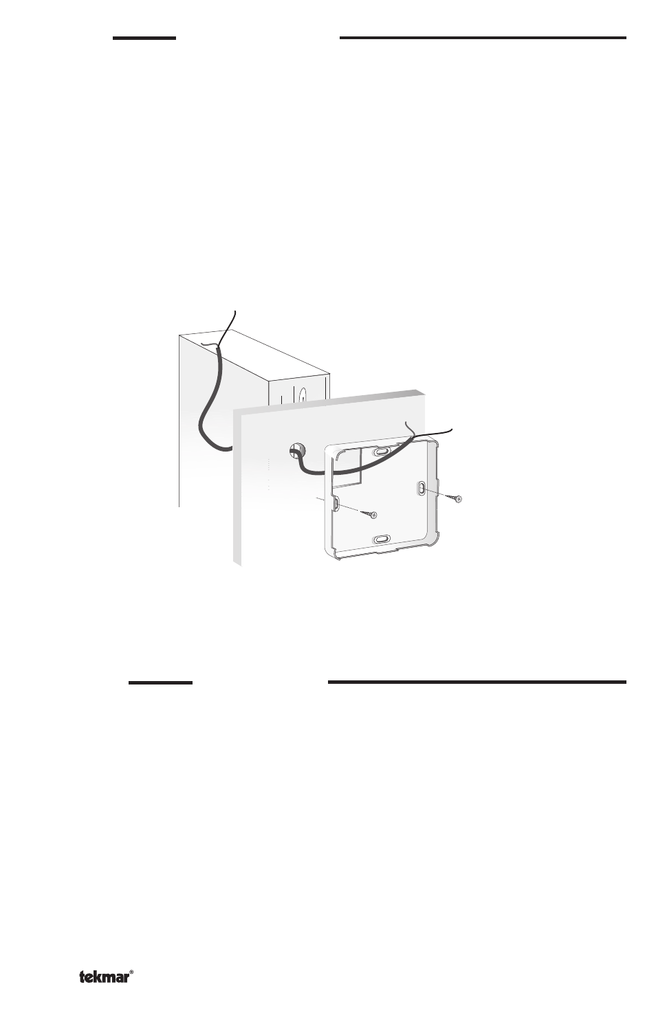
STEP TWO
MOUNTING THE RTU
The RTU should be installed on an interior wall of the desired zone to be controlled. Do not
mount the RTU in a location that may be affected by localized heat sources or cold drafts.
It may be necessary to install a draft barrier behind the enclosure in order to prevent air
from blowing through the wiring hole and affecting the RTU reading.
Mount the RTU directly to the wall using two #6-1” screws. The screws are inserted through
the mounting holes and must be securely fastened to the wall. If possible, at least one of
the screws should enter a wall stud or similar surface. If local code requires that the RTU
be mounted to a 2” x 4” electrical box, order an Adapter Plate 007. This plate will mount to
the electrical box and the RTU will then mount to the plate. Ensure that the electrical box
does not provide cold air to the RTU.
To Control
#6 1” screws