Siren with progressive switch – SoundOff Signal Directional Arrow Switch User Manual
Page 7
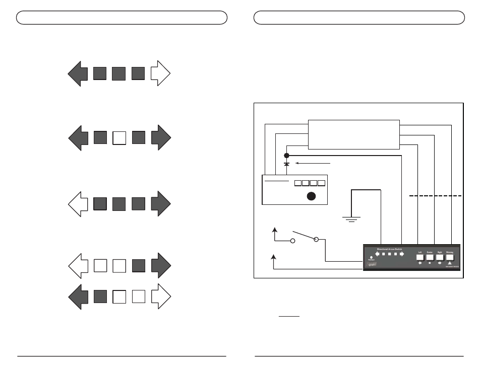
If a siren with a Progressive switch is installed in your vehicle, and you wish to
monitor/override the output of your progressive switch, the directional arrow switch can still be
used. Connect the Directional arrow switch as indicated below, then connect the output of
your Progressive switch to the desired line. The Directional Arrow Switch will indicate which
line is active.
SIREN WITH PROGRESSIVE SWITCH
Pressing the “Left” Button will apply power to the Blue wire (Left Arrow Direction), and display the
left arrow pattern on the yellow LED’s.
Pressing the “Center” button will apply power to the Brown Wire (Center Arrow Direction), and
display the center out pattern on the yellow LED’s.
Pressing the “Right” button will apply power to the Green wire (Right Arrow Direction), and display
the right arrow pattern on the yellow LED’s.
Pressing the “Warning button will apply power to the Pink and Yellow Wire, and display an
alternating pattern on the yellow LED’s.
PROGRESSIVE SWITCH
ETL 5000 INPUTS
1 2 3
GREENGREEN
BROWN
BLUE
YELLOW/WHITE
VIOLET/WHITE
ORANGE/WHITE
+10-30Vdc
+10-30Vdc
RED
WHITE/RED
BLACK
GROUND
CUSTOMER INSTALLED
DIODE MUST BE 1 Amp
OR GREATER. See note
below.
YELLOW
IMPORTANT!: Customer installed diode (i.e. 1N4004) shown
above MUST be installed or damage to the Directional Arrow
Switch could occur.
DIRECTIONAL ARROW SWITCH
PAGE 6
DIRECTIONAL ARROW SWITCH
PAGE 9