Instructions for led traffic master: ettmledw3, Changing between warning output options, Directional arrow switch page 4 – SoundOff Signal Directional Arrow Switch User Manual
Page 5: Directional arrow switch page 11
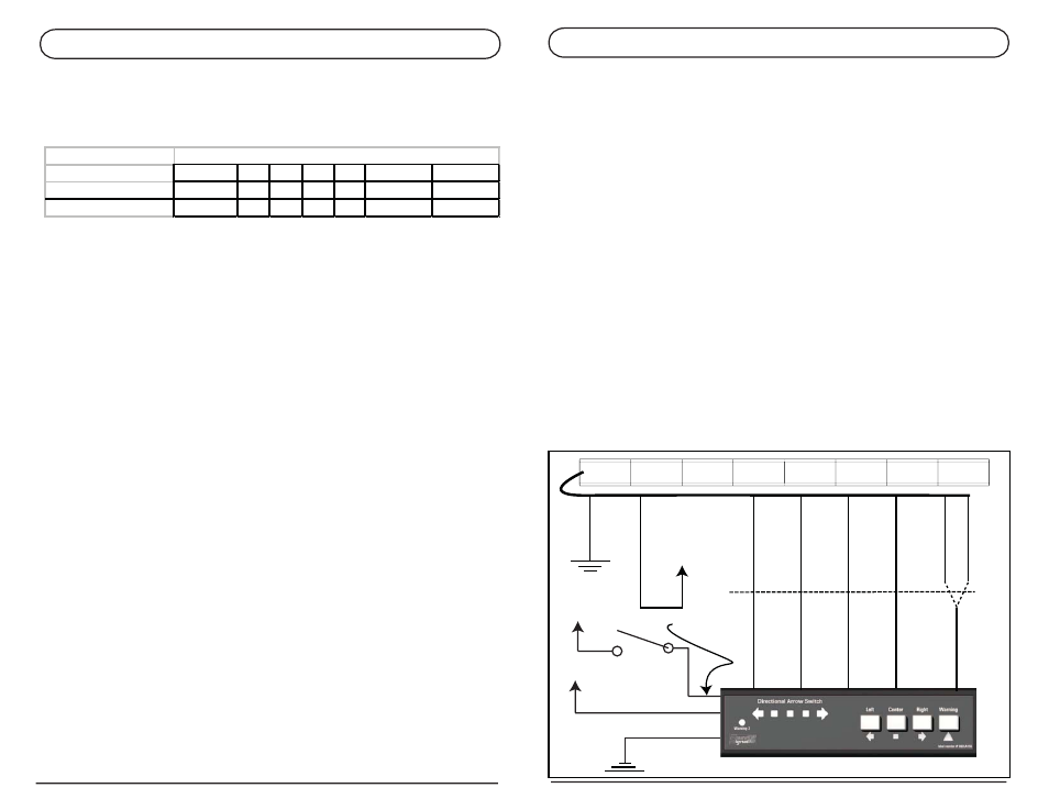
DIRECTIONAL ARROW SWITCH
PAGE 4
INSTRUCTIONS FOR LED TRAFFIC MASTER:
ETTMLEDW3
(STANDARD WIRING SETUP: LOOKING AT BAR, CABLE EXITS ON THE LEFT REAR)
Pink Wire (Warning Two)
Connect to Pink Wire of the Traffic Master
Yellow Wire (Warning One)
Connect to either the Green or Purple wire of the traffic master (depending on the desired
flash pattern)
Blue Wire (Left Arrow Direction)
Connect to Dark Green wire of the Traffic Master.
Brown Wire (Center Arrow Direction)
Connect to Yellow wire of the Traffic Master.
Green Wire (Right Arrow Direction)
Connect to Blue wire of the Traffic Master.
Please see page 10 for instructions on how to change between center output options.
Configure to apply power to the brown wire (Center Option 1)
Note: If you are using optional wiring, then the Dark Green and Blue wires must swap.
Blue Wire (Left Arrow Direction)
Connect to the Blue wire of the Traffic Master
Green Wire (Right Arrow Direction)
Connect to the Dark Green wire of the Traffic Master.
Note: End Warning can be used with the other arrow functions at the same time. With the
Warning two RED LED illuminated, pressing any of the arrow functions to have the end
warning on as well as the center lights of the traffic Master On. To turn off the end warning,
press the warning button. To turn off the arrow functions press the arrow button.
BLACK
GROUND
+10-30Vdc
RED
GREEN
PURPLE
PINK
BLUE
YELLOW
DRK. GREEN
YELLOW
PINK
GREEN
BROWN
BLUE
Either-or
NOT BOTH
DIRECTIONAL ARROW SWITCH
PAGE 11
1
2
3
4
5
6
(Default)
7
Warning Mode One DW+EW DW EW DW EW
DW
EW
Warning Mode Two
NA
EW DW
NA
NA
DW+EW
DW+EW
Warning Mode Options
Changing between Warning output options:
Pressing the Warning button while in product configuration mode will change the outputs the warning
button controls. Below is a table of options
Directional Warning (DW) will apply voltage to the Yellow Wire (Warning One Output). End Warning
(EW) will apply voltage to the pink wire (Warning Two Output).
In modes 1,4, and 5 there is no warning mode two.
In modes 2,3,6, and 7 pressing the warning button once will activate warning mode one. Pressing the
warning button twice will activate warning mode two. To exit either warning mode, press the warning
button once.
The Current Warning Mode Option is designated by the yellow LEDs.
1.
Warning Mode setting 1 is designated by yellow LED 1.
2.
Warning Mode setting 2 is designated by yellow LED 2.
3.
Warning Mode setting 3 is designated by yellow LED 3.
4.
Warning Mode setting 4 is designated by yellow LED 4.
5.
Warning Mode setting 5 is designated by yellow LED 5.
6.
Warning Mode setting 6 is designated by yellow LED 1 and 5.
7.
Warning Mode setting 7 is designated by yellow LED 1, 2, and 5.
Note: If the warning 2 RED LED is illuminated and an arrow button is pressed, they will both be on at
the same time. Pressing the Warning button will turn of the Warning 2 output. Pressing the arrow
button that is green will turnoff the Arrow Function.
To exit product configuration mode:
By holding down the Left and Warning Buttons together for 2 seconds, product configuration mode
can be exited. The unit will emit two short beeps. At this time release the buttons.
+10-30Vdc
+10-30Vdc
RED
WHITE/RED
BLACK