Directional arrow switch page 3, Directional arrow switch page 12 – SoundOff Signal Directional Arrow Switch User Manual
Page 4
DIRECTIONAL ARROW SWITCH
PAGE 3
INSTRUCTIONS FOR CONNECTION WITH ETL 5000
WITH 4-WIRE ARROW CONTROLLER OPTION
Yellow Wire (Warning One)
Connect to Arrow Warning function on ETL 5000 or ETL5000 DSC technology breakout box
input.
ETL 5000 w/ Control Cable: BLACK/WHITE
ETL 5000 w/DSC: Breakout Box Arrow, WARNING input
Blue Wire (Left Arrow Direction)
Connect to Arrow Left function ETL 5000 or ETL5000 DSC technology breakout box input.
ETL 5000 w/ Control Cable: ORANGE/WHITE
ETL 5000 w/DSC: Breakout Box Arrow, LEFT input
Brown Wire (Center Arrow Direction)
Connect to Arrow Center out function on ETL 5000 or ETL5000 DSC technology breakout
box input.
ETL 5000 w/ Control Cable: VIOLET/WHITE
ETL 5000 w/DSC: Breakout Box Arrow, CENTER input
Green Wire (Right Arrow Direction)
Connect to Arrow Right function on ETL 5000 or ETL5000 DSC technology breakout box
input.
ETL 5000 w/ Control Cable: YELLOW/WHITE
ETL 5000 w/DSC: Breakout Box Arrow, RIGHT input
NOTE: POWER CONTROL (Red/Black Wire) AND WARNING 2 (Pink Wire) OUTPUTS ARE
NOT USED.
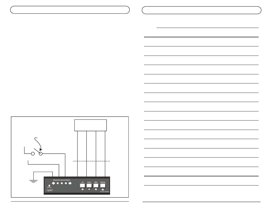
BLACK
+10-30Vdc
RED
+10-30Vdc
WHITE/RED
ETL 5000 INPUTS
GREEN
BROWN
BLUE
YELLOW
ARROW RIGHT
ARROW CENTER
ARROW LEFT
ARROW W
ARN.
DIRECTIONAL ARROW SWITCH
PAGE 12
Ignition or Master
Power Switch
NOTES: