Connecting the wires – SoundOff Signal Directional Arrow Switch User Manual
Page 3
DIRECTIONAL ARROW SWITCH
PAGE 2
CONNECTING THE WIRES:
Black Wire (Ground)
Connect to Reliable Ground
To minimize field service issues, it is recommended that the ground wires be
connected directly to the ground terminal of the battery.
Red Wire (Power Input)
Connect to a reliable +12v or +24v power source
White / Red Wire (Master / Ignition switch)
Connect to a reliable +12v or +24v power source
For the remaining wires, see the specific instructions listed below with page numbers to
distinguish which method best suits your application.
ETL 5000 with 4 - wire Arrow Controller Option ...................................................................pg. 3
LED Traffic Master ETTMLEDW3(x) .....................................................................................pg. 4
Predator Warning Bar EPRD4MD0(x), EPRD6MD0(x) or EPRD8MD0(x).............................pg. 5
Integrating DAS w/ETL 5000 & 300 Series Siren System......................................................pg. 6
LED ULTRA-LITE (EL3H08A10(x), E3H12A10(x) or (E3H12A20(x)).....................................pg. 7
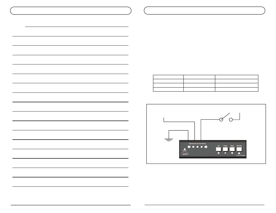
BLACK
+12Vdc
RED
+12Vdc
WHITE/RED
Wire Color
Function
Connection
Black Ground Reliable Ground
Red
Constant power
+12v or +24v
White w/ Red
Switch
Master/Ignition switch
DIRECTIONAL ARROW SWITCH
PAGE 13
NOTES: