Revel i20/i30 in-wall owner’s manual, Installation instructions – Revel I30 User Manual
Page 13
13
Note
•
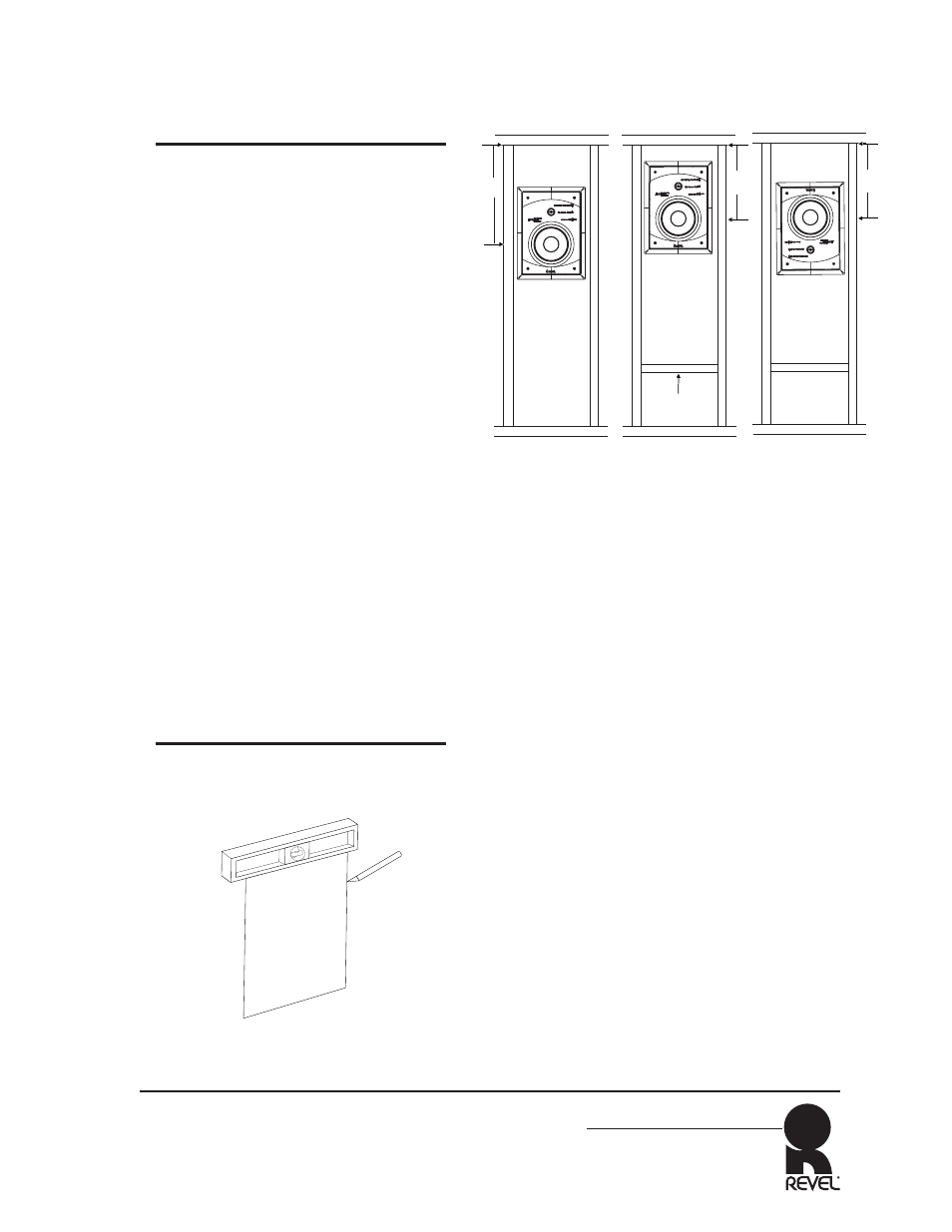
The height of the woofer within the
stud bay relative to the entire height
of the bay is critical because of
standing waves within the cavity.
•
Before installation, determine the
height of the cavity. (There might be
a fire block that makes it shorter
than the entire height from the floor
to the ceiling). Avoid placing the
woofer at the very top or bottom of
the stud bay, as this would cause a
serious cancellation of low frequency
output.
•
The ideal location for the woofer
(whether the speaker is mounted
upright or inverted) is at the one-
third distance point as shown in
example A of Figure 11 (next col-
umn). If that is not feasible, then
two-fifths, or one-fifth of the height
are the next best alternatives. The
least desirable position to place the
woofer is at one-half or one-fourth
of the height. If a fire block is
completely dividing the bay, the
measurement would be from the fire
block – not the floor or ceiling as
shown in example B of Figure 11
(next column). Example C shows an
inverted speaker placement.
2. With a utility knife, cut the wall open-
ing as shown in Figure 10 (previous
column).
•
Use caution not to cut into any
electrical wiring or plumbing. Run
the wiring from your system to the
hole. (Be sure to comply with local
wiring codes).
•
The measurements of the
opening(s) required to mount the
Revel in-wall frames are listed
below:
•
Revel I20
Width: 10.5-inch (266.7mm)
Height: 14.875-inch (377.8mm)
•
Revel I30
Width: 12.5-inch (317.5mm)
Height: 19.125-inch (485.8mm)
3. The speakers are shipped with the
baffle assembly attached to the mount-
ing frame at its four corners. Unscrew
the four screws and carefully lift the
baffle assembly out of the mounting
frame as shown in Figure 12 (next
page).
Continued on next page
REVEL I20/I30 In-wall
Owner’s Manual
Carpenter's level
Utility Knife
Figure 10: Cut wall opening
Place Woofer at
1/3 the height
of Stud Bay
1/3 the height
of Stud Bay
(measured from
the Fire Block)
Fire Block
A
B
1/3 of
Height
1/3 of
Height
1/3 the height
of Stud Bay
(measured from
the Fire Block)
1/3 of
Height
C
Figure 11: Ideal Height of Woofer
Installation Instructions
(continued)