Aileron servo installation – E-flite Piper L-4 Grasshopper 250 ARF User Manual
Page 14
14
E-flite Piper L-4 Grasshopper ARF Assembly Manual
Aileron Servo Installation
Required Parts
Fuselage assembly Flight battery
Radio system
Wing panel (right and left)
Hardwood servo mounting block (4)
Servo with hardware (2)
Aileron pushrod wire, 2
3
/
8
-inch (61mm)
1.5mm x 5mm sheet metal screw (8)
2mm x 4mm machine screw (2)
Micro brass pushrod connector with backplate (2)
Required Tools and Adhesives
Threadlock
Pencil
Pin vise
Phillips screwdriver: #00, #0
Medium CA
Medium grit sandpaper
Hobby knife with #11 blade
Drill bit: 1/16-inch (1.5mm), 5/64-inch (2mm)
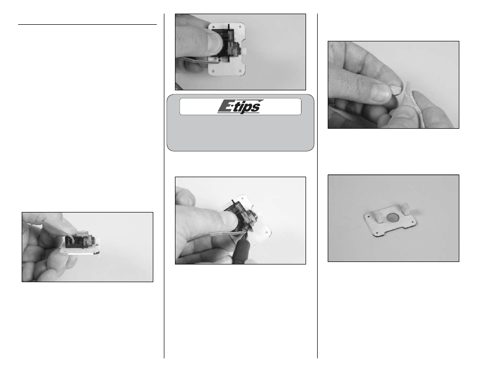
1. Remove the aileron servo cover from one wing
panel. Place the aileron servo on the cover so the
servo arm is aligned with the edge of the cover and
centered in the slot as shown. Make sure the servo
does not hang over the edges of the servo cover.
It may be necessary to remove the servo horn
from the servo so it can be properly positioned on
the servo cover. Use a #00 Phillips screwdriver to
remove and reposition the servo horn if necessary.
2. Use a pencil to trace the outline of the edges of
the servo and tabs onto the aileron servo cover.
3. Use medium grit sandpaper to roughen the end
of the servo mounting blocks that will fit against the
aileron servo cover.
4. Use medium CA to glue two servo mounting
blocks to the aileron servo cover against the outside
of the lines that were drawn. Allow the CA to fully
cure before proceeding.