E-flite Stearman PT-17 15e ARF User Manual
Page 8
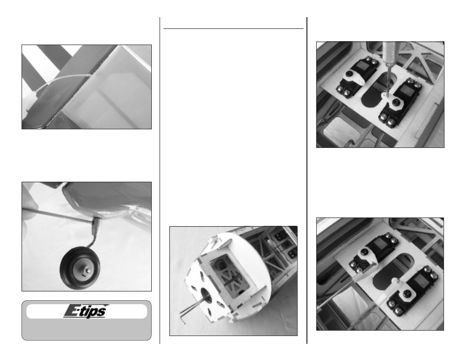
Ο 16. Apply a few drops of thin CA to each rudder
hinge. Do not use accelerator on the hinges so the
CA can penetrate the hinges completely.
Ο 17. Install the tailwheel using the supplied 1.5mm
Allen wrench. Apply a small amount of threadlock
to the setscrew before installation to prevent it from
vibrating loose.
Rudder and Elevator Pushrod Installation
Parts Required
Fuselage assembly
Elevator pushrod wire, 16-1/2-inch (419mm)
Rudder pushrod wire, 17-3/4-inch (451mm)
Nylon control horn backplate (2)
2mm x 10mm machine screw (4)
Nylon control horn (2)
Nylon clevis (2)
Nylon pushrod keeper (2)
Silicone keeper (2)
Tools Required
Pin vise
1/16-inch drill bit
Pliers
Ruler
Felt-tipped pen
Thin CA
Philips screwdriver #0
Sidecutters
Ο 1. Locate the rudder and elevator pushrods. The
longer pushrod is for the rudder and installed on
the left hand side. The shorter pushrod is installed
on the right hand side for the elevator.
Insert the pushrods in the guide tubes by feeding
them into the fuselage through the opening in the
center of the firewall.
Ο 2. Use a 1/16-inch drill bit in a pin vise to enlarge
the outer hole in the rudder servo arm and the
inner hole in the elevator servo arm.
Ο 3. Fit the pushrods to the servo arms and secure with
the pushrod keepers. Note that the elevator
pushrod is installed inverted so that the bend in the
wire does not contact the servo case.
E-flite Stearman PT-17 15e ARF Assembly Manual
8
8
Use threadlock on all metal-to-metal fasteners to
keep them from vibrating loose.