E-flite Stearman PT-17 15e ARF User Manual
Page 16
1
166
E-flite Stearman PT-17 15e ARF Assembly Manual
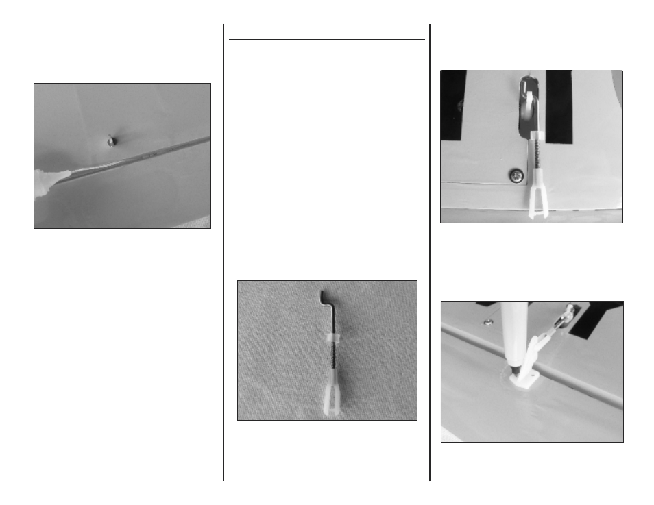
ΟΟ 6. Apply a few drops of thin CA to each of the
three aileron hinges. Do not use accelerator as
the CA needs to penetrate the hinges fully for a
complete bond.
Ο 7. Repeat steps 1 through 6 for the opposite lower
wing panel.
Aileron Linkage Installation
Parts Required
Lower wing panels w/ailerons (L & R)
Aileron wire pushrods, 1-5/8-inch (41mm) (2)
2mm x 10mm sheet metal screws (4)
Nylon control horn (2)
Nylon clevis (2)
Silicone keeper (2)
Tools Required
1/16-inch drill bit
Pin Vise
Felt-tipped pen
Low-tack tape
Philips screwdriver #0
ΟΟ 3. Attach a control horn to the clevis and mark the
mounting hole locations with a felt-tipped pen.
ΟΟ 2. Insert the pushrod into the outer hole in the
servo arm and adjust the clevis so that the clevis
pin is aligned with the aileron hinge line.
ΟΟ 1. Install a silicone keeper and nylon clevis on to a
1-5/8-inch (41mm) aileron pushrod.
- Habu 32x DF ARF (84 pages)
- A6M5 Zero 300 BNF Basic (17 pages)
- Hawker Sea Fury 480 ARF (28 pages)
- Mystique RES 2.9m ARF (52 pages)
- Super Cub 25e ARF (48 pages)
- AT-6 Texan 25 ARF (52 pages)
- LR-1A Pogo ARF 15e (21 pages)
- J-3 Cub 450 (40 pages)
- Hawker Hurricane 25e PNP (26 pages)
- Hawker Hurricane 25e PNP addendum (1 page)
- Apprentice 15e PNP (28 pages)
- Sukhoi SU-26m 480 ARF (28 pages)
- Beechcraft Bonanza 15e ARF (60 pages)
- Byp Yak 3D ARF (40 pages)
- Ultimate Fx 3D ARF (40 pages)
- Tribute FX 3D ARF (28 pages)
- Sobre 3D Profile (32 pages)
- Ascent EP Park Glider ARF (23 pages)
- Float Set Complete: Carbon-Z Cub (2 pages)
- Carbon-Z Cub PNP (27 pages)
- Carbon-Z Cub PNP Addendum (1 page)
- BAe Hawk 15 DF ARF (36 pages)
- Edge 540QQ 280 BNF Basic (19 pages)
- P-40 Warhawk 300 ARF (20 pages)
- Hawker Sea Fury 400 ARF (40 pages)
- Clipped Wing Cub 250 ARF (40 pages)
- T-34 Mentor 25e ARF (28 pages)
- Ultra Stick 25e ARF (40 pages)
- Ultra Stick 25e ARF Programming Guide (5 pages)
- Slick 3D 480 ARF (48 pages)
- PT-19 450 ARF (44 pages)
- Extra 330SC BP 3D ARF (40 pages)
- Cap 232 BP ARF (44 pages)
- Brio 10 ARF (56 pages)
- Park 480 BL Motor Combo (4 pages)
- Mini Edge 3D ARF (44 pages)
- Cessna 182 370 ARF (32 pages)
- Cessna 182/Park 400 BL Motor Combo (4 pages)
- Tribute 3D Profile ARF (40 pages)
- Fokker DVII 250 ARF (28 pages)
- Enticement F3P ARF (36 pages)
- Carbon-Z Yak 54 3X BNF Basic (23 pages)
- Carbon-Z Scimitar PNP (28 pages)
- UMX B-17G Flying Fortress BNF (18 pages)
- UMX Sbach 342 3D BNF Basic (17 pages)