Reverse osmosis module mounting, Green tube connection, Connect the red tube from faucet to ro module – Watts PWRO5MAN User Manual
Page 6: Drain saddle tube connection, Step 6 step 5, Step 7, Step 4
6
Reverse Osmosis Module Mounting
Step A – Determine best location for the
RO module to be mounted to
allow for future system main-
tenance . The parts bag has 2
self-tapping screws . Using an
electric drill with a Phillips bit,
screw them into the cabinet
wall 6" apart and 16" from the
bottom of the cabinet .
Note: Do not cut any RO system tubes at this time.
STEP 6
STEP 5
Green Tube Connection
Step A – Locate green tube attached to the
RO Module . Insert the open end of
the green
1
⁄
4
" tube into the open
1
⁄
4
"
Quick-Connect fitting on the Adapt-
A-Valve™ making sure the tube is
pushed in all the way to the tube
stop .
Step B – Connect the green tube from the RO
module to the Adapt-A-Valve™ that
is connected to the angle stop valve .
Leave enough tube so it is not kinked and cut the tube to
the desired length .
Step A – Insert the red
1
⁄
4
" tube from
the faucet into the port on the
module marked DRAIN . Make
sure the tube is pushed in all
the way to the tube stop .
Connect the Red Tube from
Faucet to RO Module
STEP 7
Drain Saddle Installation -
Fits standard 1¼" – 1½" drain pipes
Follow all local plumbing codes for your installation.
Caution: If you have a garbage disposal, do not install the drain
saddle near it. Installation of the drain saddle must be either
above the garbage disposal, or if a second sink drain is avail-
able, install it above the cross bar on the second drain. Installa-
tion of the drain saddle near a garbage disposal may cause the
drain line to plug.
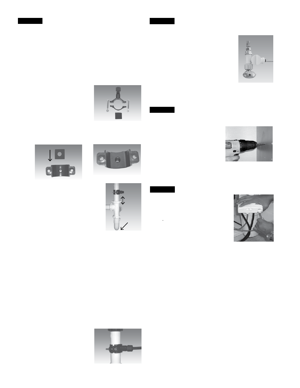
Step A – Locate the drain saddle kit in the parts bag .
Gather the pieces of the drain saddle
( 1 ) - Black compression nut
( 1 ) - Semicircle bracket with opening
( 2 ) - Screws
( 1 ) - Foam gasket
( 2 ) - Nuts for screws
( 1 ) - Semicircle bracket
Step B – The small square black foam gasket with a circle cut out
of the middle must be applied to the inside of the drain
saddle . Remove sticky tape backing and stick to the drain
saddle as shown .
Step C – The drain saddle must be installed
at least 1 ½" above the nut of the
P-Trap elbow or cross bar from the
garbage disposal to insure proper
drainage . Using the 1/4" drill bit,
drill into the drain pipe at best avail-
able location as specified above,
for drain saddle installation . Take
extreme caution to only drill through
one side of the drain pipe .
Step D – Assemble the drain saddle around the drain pipe and align
drain saddle fitting opening with the hole drilled in the
previous step - you may use a small screwdriver to feed
through the drain saddle into the drain pipe to aid with the
alignment . Using a Phillips screw driver tighten the drain
saddle bolts evenly and securely on both sides .
Caution: Do not over tighten the screws. It may crack the drain
saddle.
Drain Saddle Tube Connection
The black 3/8" drain tube must be as SHORT and STRAIGHT as
possible to the drain saddle, making a downward slope from faucet
to drain saddle to allow for proper drainage . This is a gravity fed line
and if there is any bend or dip in the tube, the rinse water will not
flow into the drain properly . Water may back up and come out the air
gap hole in the back of the faucet .
Step A – Measure the 3/8" drain tube from faucet to the drain saddle
on the drain pipe and make a straight cut to the correct
length .
Step B – Slip drain tube through black
compression nut . Insert drain
tube into the opening in the
drain saddle and hand tighten
the black nut, and add 1/4 turn
with a wrench .
STEP 4
1.5"
P-Trap
Elbow