Hinkley Lighting THISTLEDOWN 4170VZ User Manual
Start here, Assembly instructions
assembly instructions
Family: Thistledown Item No. 4170 VZ
1. Find a clear area in which you can work.
2. Unpack fixture and glass from carton.
3. Carefully review instructions prior to assembly.
*** The construction of this fixture will be accomplished by first assembling the
basic fixture, mounting the mounting strap to the junction box, making all
necessary electrical connections, hanging the fixture from the ceiling, and then
installing the glass.
start here
4170
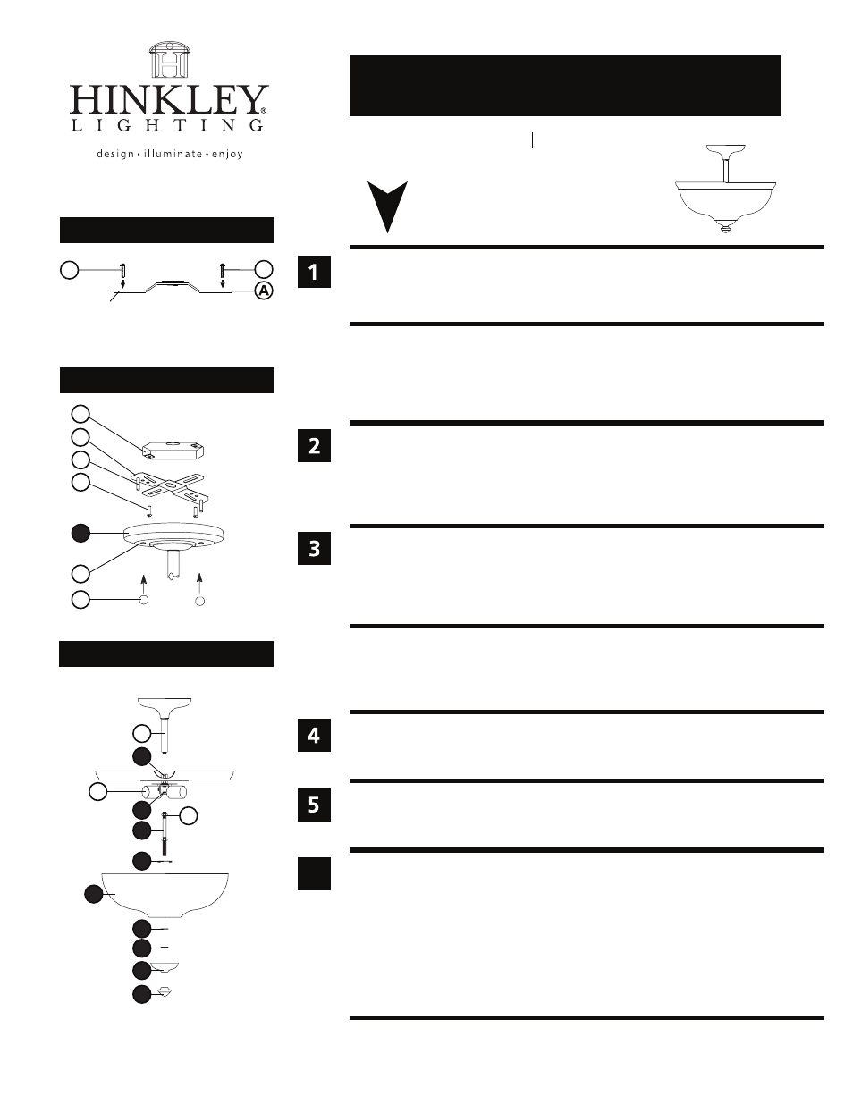
Drawing 2 - Fixture Mounting
Drawing 3 - Fixture Assembly
B
D
F
J
C
A
1. Prepare gem strap (A) for mounting by threading two screws (B) provided into
back of gull wing bracket of gem strap (A) - see Drawing 1.
• Be sure the holes into which the screws are threaded match the spacing of holes (D)
in the ceiling pan (1) - see Drawings 1 and 2.
2. Mount gem strap (A) to junction box (J), using the two 1” screws (C) provided.
1. To assemble fixture, thread center column assembly (E) into coupler (9) located on
the top of body assembly (G) - see Drawing 3.
2. Thread center stem (2) into coupler (10), located on the bottom of the main body
assembly (G), approximately 3/8”.
3. Thread hex nut (H) against coupler (10) to secure center stem (2) to fixture.
Make electrical connections from supply wire to fixture lead wires. Refer to instruction
sheet (I.S. 18) and follow all instructions to make all necessary wiring connections.
Then refer back to this sheet to continue installtion of this fixture.
1. To hang the fixture, slip the holes (D) in the ceiling pan (1) over the screws (B) in
the mounting strap (A) - see Drawing 2.
2. Thread on ball knobs (F) to secure fixture to the ceiling.
1. Prior to installing glass, fixture should be lamped.
2. To install glass, slip flat washer (3) onto center stem (2) and hold in position - see
Drawing 3.
3. Slip glass (4) onto center stem (2) and up aginst ring (E) and hold in position..
4. Slip flat washer (5) onto center stem (2) and hold in position.
5. Thread knurl nut (6) onto center stem (2) and tighten to secure glass.
6. Slip cap (7) onto center stem (2) and hold in position.
7. Thread bottom knob (8) onto center stem (2) and tighten.
SAFETY WARNING: READ WIRING AND GROUNDING INSTRUCTIONS (I.S. 18)
AND ANY ADDITIONAL DIRECTIONS. TURN POWER SUPPLY OFF DURING
INSTALLATION. IF NEW WIRING IS REQUIRED, CONSULT A QUALIFIED
ELECTRICIAN OR LOCAL AUTHORITIES FOR CODE REQUIREMENTS.
Drawing 1 - Strap Detail
B
(side view)
gull wing
bracket
B
1
E
H
G
9
2
10
6
4
3
5
6
8
7
2.7.08
H I N K L E Y L I G H T I N G 33000 Pin Oak Parkway Avon Lake, OH 44012 800.446.5539 / 440.653.5500 hinkleylighting.com