Start here, Commencez ici, Empezar aquí – Hinkley Lighting GATSBY 4935PL User Manual
Page 2: 4935hi, Hanging instructions, Instructions suspendues, Instrucciones que cuelgan
H I N K L E Y L I G H T I N G 33000 Pin Oak Parkway Avon Lake, OH 44012 800.446.5539 / 440.653.5500 hinkleylighting.com
4935HI
hanging instructions
start here
SAFTEY WARNING: READ WIRING AND GROUND INSTRUIONS (I.S.18)
AND ANY ADDITIONAL DIRECTIONS. TURN POWER SUPPLY OFF
DURING INSTALLATION. IF NEW WIRING IS REQUIRED, CONSULT A
QUALIFIED ELECTRICIAN OR LOCAL AUTHORITIES FOR CODE
REQUIREMENTS.
1. Shut off electrical current before starting. If the fixture you are
replacing is turned on and off by a wall switch, simply turn the
switch off. If not, remove the appropriate fuse (or open the circuit
breakers) until the fixture is dead.
• DO NOT restore current – either by fuse, breaker or switch – until the
new fixture is completely wired and in place.
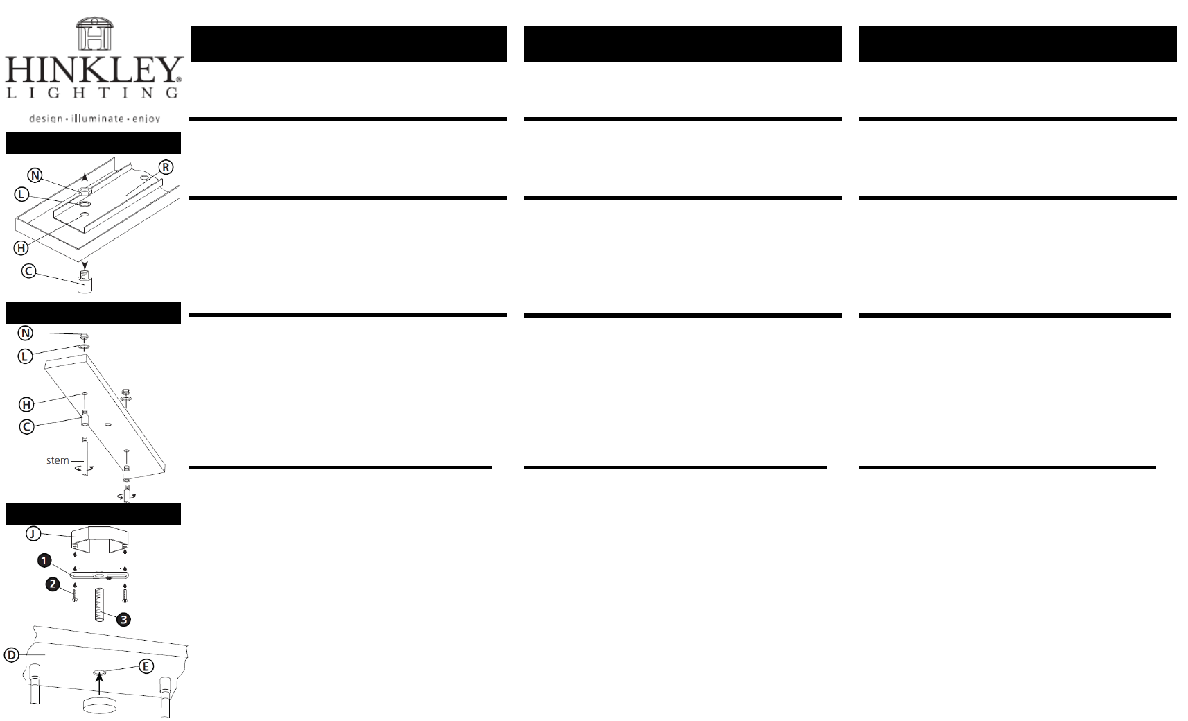
1. To assemble fixture it is necessary to first remove the couplers (C)
from canopy (D) – see Drawing 1.
NOTE: re-enforcement bracket (R) located in canopy will be loose
after couplers (C) are removed. Make sure this is re-attached later.
2. This is accomplished by removing hex nut (N) and lock washer (L)
form the threaded portion of coupler (C), and removing the coupler
from hole (H) of the canopy.
3. Set removed parts aside to be used later during the assembly
process.
1. Fasten mounting strap (1) to outlet box (J) with the original outlet
box screws (2) – see Drawing 3.
2. Thread nipple (3) into mounting strap (1) approximately 3/8”.
3. Make electrical connections from supply wire to fixture lead wires.
Refer to instruction sheet (I.S. 18) and follow all instructions to
make all necessary wiring connections.
4. Slip center hole (E) of canopy (D) over nipple (3) and slide up till
canopy is against ceiling. Hold fixture in position.
5. Thread decorative final (5) onto end of nipple (3) and tighten to
secure fixture to ceiling.
4935HI
instructions suspendues
commencez ici
AVERTISSEMENT DE SECURITE: LIRE CABLAGE ET INSTRUCTIONS DE
MISE (I.S.18), ET TOUTE AUTRE INSTRUCTION. COUPER
L’ALIMENTATION ELECTRIQUE PENDANT L’ONSTALLATION. SI DE
NOUVELLES CABLAGE N’EST NECESSAIRE, CONSULTEZ UN
ELECTRICIEN QUALIFIE OU AUTORITES LOCALES POUR EXIGENCES DU
CODE.
1. Couper le courant électrque acant de commencer. Si l’appareil vous
remplacez est activé et désactivé par un interrupteur mural, il suffit
de tourner l’interrupteur. Sinon, retirez le fusible approprié (ou
ouvrez les disjoncteurs) jusqu’à ce que l’appareil est mort.
• NE PAS restaurer actuel – soit par fusible, disjoncteur ou
interrupteur – jusqu’à ce que le nouvel appareil est entièrement
cable et en place.
1. Pour assembler appareil, il est nécessaire d’enlever d’abord les
coupleurs (C) de la canopée (D) – Voir Schéma 1.
REMARQUE: Le support re-application (R) situé dans la canopée
sera libre après coupleurs (C) sont supporimés. Assurez-vous que
cela est remis en place plus tard.
2. Ceci est realize en enlevant l’écrou hexagonal (N) et la rondelle de
blocage (L) forment la partie filetée du raccord (C), et le retrait du
coupleur de trou (H) de la voilure.
3. Réglez les pieces retirees de côté pour être utilize plus tard au cors
du processus d’assemblage.
1. Fixer sangle de fixation (1) à la boîte de sortie (J) avec les vis de la
boîte de sortie d’origine (2) – Voir Schéma 3.
2. Mamelon de filetage (3) en bande de montage (1) d’environ 9.525
mm.
3. Effectuez les connexiones électriques du cable d’alimentation à fils
de connexions du projecteur. Reportez-vous à la feuille d’instruction
(I.S. 18) et suivez toutes les instructions pour effectuer tous les
branchements nécessaires.
4. Glissez le trou central (E) de la carrosserie (D) sur mamelon (3) et
glisser vers le haut jesqu’à ce verrière est contre plafond. Tenir
l’appareil en position.
5. Discussion finale decorative (5) sur l’extrémité du mamelon (3) et
serrer pour sécuriser luminaire au plafond.
4935HI
Instrucciones que cuelgan
empezar aquí
ADVERTENCIA DE SEGURIDAD: LE LAS INSTRUCCIONES DE
CABLEADO Y LA TIERRA (I.S.18), E INSTRUCCIONES ADICIONALES.
APAUGE LA ALIMENTACIÓN DE CORRIENTE DURANTE LA
INSTALACIÓN. SI SE REQUIERE NUEVO CABLEADO, CONSULTE CON
UN ELECTRICISTA O AUTHORIDADES LOCALES PARA REQUISTOS
DEL CÓDIGO.
1. Apague la corriente eléctrica antes de comenzar. Si el aparato va a
sustituir se enciende y se apage por un interruptor de pared,
simplemente gire el interruptor. Si no es así, quite el fusible
adecuado (o abra los interruptores de circuito) hasta que el
aparato está muerto.
• NO restaurar actual – ya sea mediante fusible, disyuntor o
interruptor – hasta que el Nuevo dispositivo está completamente
conectado y en su lugar.
1. Para el montaje de fijación es necesario extraer primero los
acopladores (C) desde la cubierta (D) – Véase la Figura 1.
NOTA: El soporte de re-aplicaión de la (R) situado en el soel se
suelta después de acopladores (C) se eliminan. Asegúrese de que
este se vuelve a conectar más tarde.
2. Esto se logra mediante la eliminación de la tuerca hexagonal (N) y
la arandela de bloque (L) forman la parte roscada del acoplador
(C), y la eliminación de la acoplador del agujero (H) de la cubierta.
3. Conjunto partes retiradas a un lado para ser utilizado más adelante
durante el proceso de montaje.
1. Fije la correa de montaje (1) de la caja de salida (J) con los tornillos
de la caja de salida de originales (2) – Véase la Figura 3.
2. Nipple de rosca (3) en el soporte de montaje (1) de
aproximadamente 9.525 mm.
3. Hag alas conexiones eléctricas de los cables de alimentactión a los
cables conductors accesorio. Consulte la hoja de instrucciones
(I.S. 18) y siga las instrucciones para haver todas las conexiones
necesarias.
4. Deslice el agujero central (E) de la campana (D) a través de la
boquilla (3) y deslice hacia arriba hasta el dosel es contra el techo.
Mantener fijo en su posición.
5. Última decorative de rosca (5) en el extreme del pezón (3) y
apriete apara asegurar fixture hasta el techo.
Drawing 1 – Fixture Assembly
Drawing 2 – Glass Installation
Drawing 2 – Glass Installation