Hinkley Lighting RANDOLPH 1494 User Manual
Star t here, Assembly instructions
H I N K L E Y L I G H T I N G 33000 Pin Oak Parkway, Avon Lake, OH 44012 800.446.5539 www.hinkleylighting.com
assembly instructions
Item No. 1490 / 1494
1. Find a clear area in which you can work.
2. Unpack fixture and glass from carton.
3. Carefully review instructions prior to assembly.
*** The construction of this fixture will be accomplished by first mounting the mounting
strap to the junction box, making all necessary electrical connections, mounting the fixture
to the wall and then installing the glass.
star t here
1494
SAFETY WARNING: READ WIRING AND GROUNDING INSTRUCTIONS (I.S. 18)
AND ANY ADDITIONAL DIRECTIONS. TURN POWER SUPPLY OFF DURING
INSTALLATION. IF NEW WIRING IS REQUIRED, CONSULT A QUALIFIED
ELECTRICIAN OR LOCAL AUTHORITIES FOR CODE REQUIREMENTS.
Make electrical connections from supply wire to fixture lead wires. Refer to instruction sheet (I.S.
18) and follow all instructions to make all necessary wiring connections. Then refer back to this
sheet to continue installation of this fixture.
Glass installation Instructions - see Drawing 2.
1. To remove cage (1), remove ball knob studs (2) located inside the cage (1) near top of fixture, roof
and backplate (3) can now be removed from cage (1).
2. Remove retainer screw (4) that holds glass clip (5) in place, remove glass clip (5).
3. Slip glass panel (6) into position in cage (1). Replace clip (5) and thread retainer screw (4) to
secure clip. Repeat for remaining panels.
4. Re-attach cage (1) back onto roof (3) with ball knob studs (2) removed earlier.
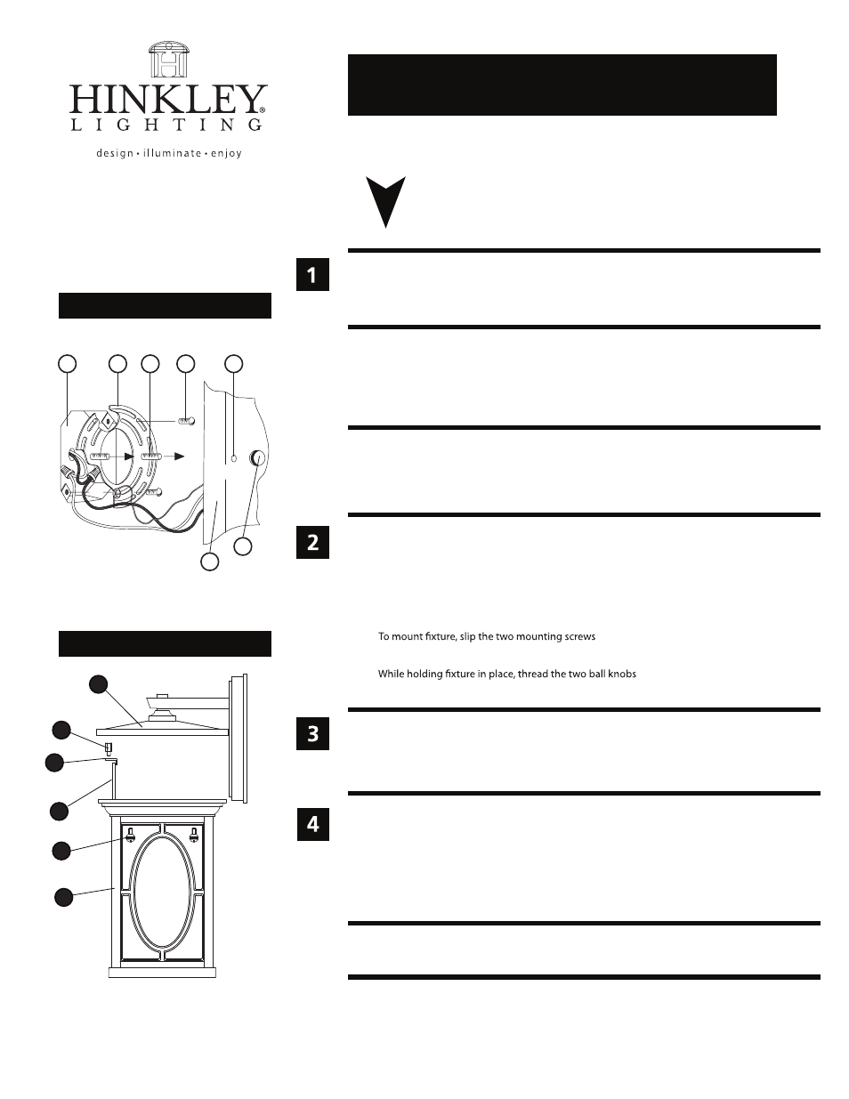
Drawing 1 - Fixture Mounting
Drawing 2 - Glass Installation
6.1.12
1490
3
4
6
5
2
1
A
J
B
C
D
E
F
back plate
1. Prepare mounting strap (A) by threading the two long mounting screws (B)
into the back of the mounting strap (A) - see Drawing 1.
• Be sure the holes into which the screws are threaded match the spacing of holes (D)
in the backplate (E).
2. Attach mounting strap (A) to junction box (J) using two screws (C).
3.
(B) through the two mounting holes (D) in the
backplate (E) - see Drawing 1.
4.
(F) on to the end of the mounting
screws (B), and tighten.
NOTE: Customer has option of installing clear seedy glass panels, or
amber linen glass panels.