Hinkley Lighting MIRAGE 53350 User Manual
Start here, Commencez ici, Empezar aquí
H
I
N
K
L
E
Y
L
I
G
H
T
I
N
G
33000
Pin
Oak
Parkway
A
von
Lake
, OH
44012
800
.446
.5539
/
440
.653
.5500
hinkley
lighti
ng.
com
Assembly
Instructions
Item No.
53350
start
here
1.
Find
a
cl
ea
r
ar
ea
in
which
y
ou
c
an
wo
rk
.
2.
Unpa
ck
fixtur
e
from
carton
.
3.
C
arefu
lly
r
ev
iew
in
str
uct
ions
prior
to
a
ss
em
bl
y.
*** The
co
n
str
u
ction
of this fix
ture will
be ac
co
mpli
shed
by fir
st
mo
u
n
ti
n
g
the
m
ount
ing str
ap t
o
the j
u
ncti
o
n
bo
x, mak
ing all
n
ecessary
electrical c
o
nn
ections,
ass
embl
ing th
e ma
in
bo
d
y of th
e fixtu
re,
mo
u
n
ti
n
g
the
fi
xture to the
wa
ll and
th
en
in
sta
lling t
h
e gla
ss.
1
. Re
m
o
ve
th
e
m
ai
n
m
ount
ing
pla
te
(A
) from
fi
xt
u
re back
p
late
(B
)
by
remo
ving the
fo
ur flat he
ad
scr
ews
(C
) – see
Draw
ing
1
.
2
. Slide
th
e wires
fr
om the
ju
n
cti
o
n
b
o
x,
th
ro
u
gh
th
e large
center
hole,
making sure
cu
rv
ed s
lots
(D
) l
in
e up wi
th
the
th
readed
holes
(E
) in
th
e j
unction
bo
x.
3
. Using t
w
o 8-32
screws
(f)
attach
the ma
in
m
o
u
n
ting
plate
(A
)
to
t
h
e
junct
ion
b
o
x,
m
aking
su
re side
of m
o
unt
ing
pl
at
e
(A
) is squar
e
to
ceilin
g
.
SA
FT
EY
W
A
RNING:
R
EAD
W
IRING
A
N
D
GR
O
U
N
D
INSTRUIO
N
S
(I.S
.18
)
AND
A
N
Y
A
D
DI
TI
ONAL
DIRE
CTIONS.
T
U
RN
POW
ER
S
U
PP
LY
O
FF
DURI
N
G
IN
STALLATION.
IF
NE
W
WIRING
IS
R
EQ
U
IRED,
CONS
U
LT
A
QUA
LI
FI
ED
ELE
CTRICIAN
OR
L
O
CA
L
AUTHORIT
IE
S F
O
R
CODE
RE
Q
U
IR
EM
ENTS
.
Make electrical
co
n
n
ecti
o
n
s fr
o
m su
p
p
ly
wire
to
fixture
lead w
ires.
Refer to instruc
tion sheet
(I
.S. 1
8
) and fol
low a
ll instructions to
make all
neces
sary wiri
n
g
c
o
n
n
ections.
1
. M
ount t
h
e fix
tu
re by sl
id
in
g th
e back
plate
(B
) over
m
o
unti
n
g
plate
(A
) – see
D
ra
w
in
g
1
.
2
. Attach the
back
plate
(B
) to the
mounting plat
e
(A
) usi
n
g the sc
rews
(C
).
Les
Instructions
D’assemblage
Numé
ro
d’artic
le: 53350
commencez ici
1.
Trou
ve
z
un
e
spa
ve
lib
re
d
an
s
leq
uel
vou
s
po
uv
ez
tr
avail
le
r.
2.
Déball
le
z
ap
pa
reil
de
la
boî
te
.
3.
Exami
ne
z
att
en
tive
m
en
t
le
s
in
str
uc
tion
s
av
an
t
le
mon
ta
ge
.
*** La
co
n
struc
tion
de ce
dis
p
o
sitif sera réalisé
selon la
prem
ièr
e de
mont
ag
e
de la
b
ride de
m
o
nta
g
e de la
boîte
de
jonct
ion, t
o
utes
les
co
n
n
exi
o
n
s él
ec
triques
néces
sa
ires, l’ass
embl
ag
e du
co
rps
prin
cipal
d
u
dis
p
ositif de fi
xation, le
m
o
nt
ag
e de
la fixati
on
à la paro
i,
p
u
is
l’installati
o
n
d
u
verre.
1
. Retirer la pl
aq
u
e de
m
ont
ag
e
p
rincipal
(A
) d
e
la pla
q
ue arrièr
e de
fi
xa
tion
(B
) en
retirant les quatre
vis à tête
plat
e
(C
)
–
Voir
Sc
h
é
ma
1
.
2
. Glisse
z les fils d
e la boîte
de
jun
ction, à tr
av
ers l
e grand trou
au
centre, faisant
que les fentes
co
urbes
(D
) s’a
lig
n
ent av
ec les tro
u
s
taraud’es
3
. Using t
w
o 8-32
screws
(f)
attach
the ma
in
m
o
u
n
ting
plate
(A
)
to
t
h
e
junct
ion
b
o
x,
m
aking
su
re side
of m
o
unt
ing
pl
at
e
(A
) is squar
e
to
ceilin
g
.
AVERTIS
SEMEN
T
DE
S
EC
U
RITE:
L
IRE
CABL
A
GE
E
T
INSTRUCTI
O
NS
D
E
M
ISE
(I
.S
.18)
, ET
T
O
UTE
A
U
TR
E
IN
STRUCTI
O
N
. C
O
U
PE
R
L’
ALI
M
EN
TAT
IO
N
ELECT
R
IQ
U
E
PE
ND
A
NT
L’INST
A
LLATION
. SI
D
E
NOUV
EL
LE
S
CA
BL
A
G
E
N
’EST
NE
CE
SSAI
R
E,
CON
SU
LT
EZ
U
N
EL
ECTRIC
IE
N
Q
U
A
LIF
IE
O
U
A
UT
O
RITE
S
LO
CA
LE
S
PO
U
R
EX
IG
EN
CE
S
D
U
CO
DE
.
Effectue
z
les conn
ex
ions électr
iques du c
able d
’alimentat
ion à
fils de
conne
xi
on
du
p
rojecteur.
Repor
te
z-
vous à la f
eu
ille d’instruction
(I
.S.
1
8
) et
su
ivez t
o
utes les in
structions
p
o
ur
effectuer tous le
s
bran
ch
em
en
ts nécessaires.
1
. Monter le di
sp
o
sitif en faisant
g
lisser la pla
q
ue
arrière
(B
) sur la
pla
q
ue de
m
o
n
tage
(A
)
–
V
o
ir
Sc
h
éma
1
.
2
. Fi
xer la pl
aque
a
rrière
(B
) à la p
laque
de
m
ont
ag
e
(A
) à l
’aide
d
es vis
(C
).
Instrucciones
De
Montaje
Núme
ro
del
artículo:
53350
empezar aquí
1.
Bu
sq
ue
un
lu
ga
r
cla
ro
en
el
q
ue
s
e
pu
ed
e
tr
ab
aja
r.
2.
D
es
em
ba
le
ac
ce
so
ri
o
de
la
c
aj
a.
3.
Revi
se
cu
id
ad
os
am
en
te
la
In
st
ru
ccio
ne
s
an
te
s
del
m
on
ta
je
.
*** La
co
n
struc
ción
de este
dis
p
ositivo
se l
o
gra
medi
an
te el
m
o
ntaje de
la primera
corr
ea de
m
ontaj
e a
la caja de
c
o
nex
iones,
por
lo
q
u
e todas
las c
o
nexi
o
n
s e
léctricas ne
cesar
ias, el
m
ontaje
d
el cuer
p
o
pr
in
ci
pal del
dis
p
ositivo
de
fi
jación
, el acc
es
o
rio de
m
o
ntaje
a la pare
d
y lu
ego
instalar el crista
l.
1
. Retire la pl
aca
p
rincipal
de
mon
taje
(A
) d
e la pl
aca de fijac
ión
trasera
(B
) reti
ran
d
o los
cu
atro
tornillos
de c
ab
eza
p
lana
(C
)
–
Vé
a
se
la
F
igu
ra
1
.
2
. Deslice los
cabl
es
de la caja
de
con
exi
o
n
es, a tr
avés del
ag
u
jero
central más
gr
ande,
haci
enda
ranuras
cu
rv
ad
as
seguro
(D
) se
alinea
n
c
o
n los
orificios rosc
ad
o
s
(E)
en la ca
ja
d
e con
ex
iones.
3
. El uso
de
d
o
s t
o
rnillos d
e 8-32
(F)
fijar la placa
de
m
ontaje
pri
n
cipal
(A
) a la caj
a de
con
exi
o
n
es,
p
o
r
lo
q
u
e parte
de
la placa
de
mont
aje
(A
) es
la pl
az
a hasta el
techo.
ADVER
TENCI
A
D
E
SE
G
U
RIDAD
: LE
LAS
INST
R
U
CC
IONES
D
E
CABLE
A
DO
Y
L
A
TIERR
A
(I.S.1
8)
, E
INSTRUCCIO
N
ES
ADICIONALES.
APAUG
E
LA
A
LI
M
EN
TACIÓN
DE
CORRIENTE
DURANT
E
LA
INSTALACIÓN.
S
I SE
R
EQU
IE
R
E
N
U
EVO
CA
BL
EA
D
O
, CONSULTE
C
O
N
UN
E
LEC
TR
ICIS
TA
O
AU
TH
ORID
A
DE
S L
O
CA
LE
S
PARA
REQUISTO
S
D
EL
CÓD
IGO.
Effectue
z
les conn
ex
ions électr
iques du c
able d
’alimentat
ion à
fils de
conne
xi
on
du
p
rojecteur.
Repor
te
z-
vous à la f
eu
ille d’instruction
(I
.S.
1
8
)
et
su
iv
ez
to
u
tes
le
s i
nstruc
ti
ons pour effec
tuer tous les
bran
ch
em
en
ts nécessaires.
1
. Monte el
ap
ara
to desl
iz
an
do
la
placa
de
m
onta
je
(B
) sobre la
p
laca
de
m
ontaje
(A
)
–
V
éa
se
l
a
F
igu
ra
1
.
2
. Fije la
placa
po
sterior
(B
) a la p
laca de
m
o
ntaje
(A
) c
o
n los to
rn
illos
(C
).
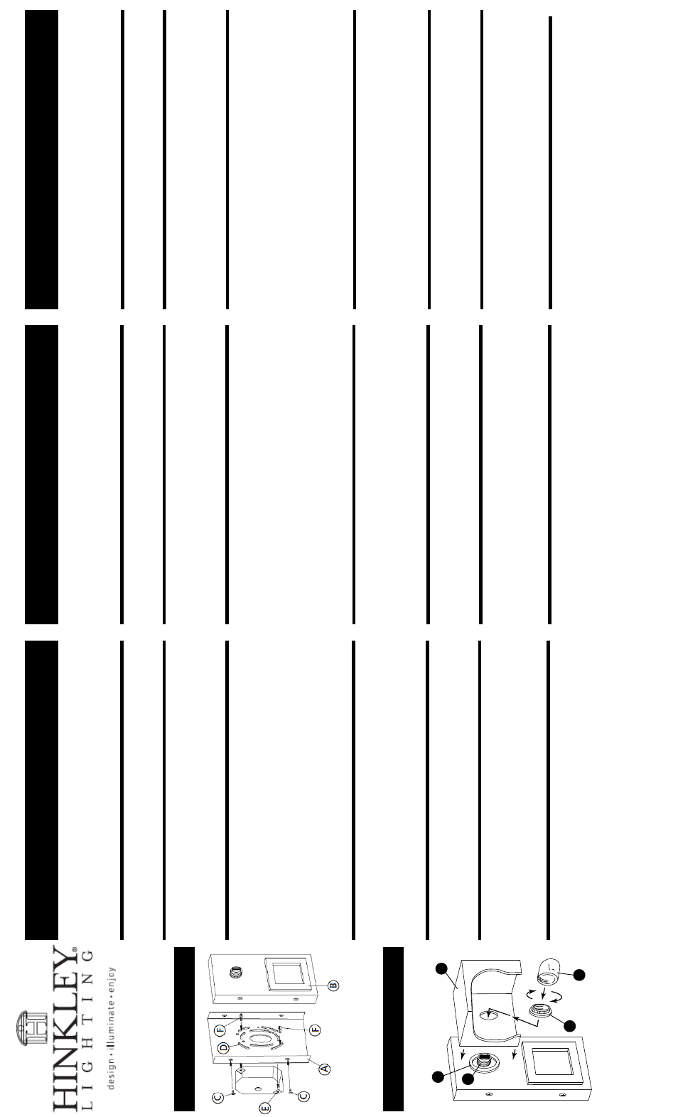
Drawi
n
g 1
– F
ixture Mo
u
n
ti
n
g
Drawi
n
g 2
– Gl
ass Installat
ion
1
2
3
4
R
1. Para instalar vidrio quitar el anillo conector (3) del casquillo (1).
2. Deslice el anillo de amortiguación (R) a través de socket (2).
3. Resbalón de vidrio (1) más de socket (2). Nota: El extremo abierto de
vidrio puede ser orientado hacia arriba, hacia abajo o hacia los lados.
Mantenga vidrio postion.
4. Anillo de rosca hembra (3) en el conector (2) y apriete hasta que
estén ajustados.
5. Accesorio se puede lamped en consecuencia en este momento.
6. Después lamping hilo bombilla escudo (4) en el conector (2).
1. Pour retirer le connecteur anneau de verre installation (3) de la
douille (1).
2. À bague d'amortissement (R) sur la douille (2).
3. Slip verre (1) sur la douille (2). Note: extrémité ouverte du
verre peut être orienté vers le haut, vers le bas ou à côté. T
enez verre
en postion.
4. Bague filetée de la prise (3) sur la douille (2) et serrer jusqu'à ce que
confortable.
5. Fixture peut être lamped en conséquence à ce moment.
6. Après lamping bouclier ampoule de fil (4) sur la douille (2).
1.
T
o install glass remove socket ring
(3)
from socket
(1)
.
3.
Slip glass
(1)
over socket
(2)
. Note: open end of glass can be oriented
up, down or to either side. Hold glass in postion.
4. Thread socket ring
(3)
onto socket
(2)
and tighten until snug.
5. Fixture can be lamped accordingly at this time.
6. After lamping thread bulb shield
(4)
onto socket
(2).
2. Slip cushion ring
(R)
over socket
(2)
.