Hinkley Lighting HELIOS FR43918SLF User Manual
Helios
Item No. 43918
Numéro d’article: 43918
Número del artículo: 43918
english
spanish
french
HELIOS
HELIOS
HELIOS
Bulbs: 60 WATT CAND.
replacement parts: FR43913GL
Bulbos: 60 vatios candelabro
piezas de recambio: FR43913GL
Ampoules: 60 watt candélabres
pièces de rechange: FR43913GL
[DRAWING 1]
A
J
B
F
F1
C
D
E
1
3
2
2
1
[DRAWING 2]
HELIOS
ASSEMBLY ENSTRUCCIONES
Montaje de este dispositivo se logra uniendo primero las
piezas de montaje de la caja de conexiones , por lo que todas
SEGURIDAD WARNING: Lea las instrucciones de cableado y
conexión a tierra [ FRIS 18 ] , e instrucciones adicionales.
Apague la fuente de alimentación durante la instalación. Si se
necesita un nuevo cableado , consulte a un electricista
del código .
S TEP 1
1 Preparar cinta de montaje ( A) , enroscando tubo roscado
2 Sujete la correa de montaje ( A) a la caja de conexiones ( J )
con dos tornillos cortos ( C ) suministrados.
3 arandela de bloqueo de deslizamiento ( F1 ) sobre la
boquilla ( C ) y la tuerca hexagonal hilo ( F ) sobre el tubo
roscado ( C ) .
4 tuerca hexagonal ( F ) se puede apretar contra la brida de
montaje ( A) después de ajustar tubo roscado ( C ) a la
longitud de montaje adecuada .
Para montar aparato a la pared agujero central de deslizamien
to de la placa posterior (E ) sobre el tubo roscado ( C ) y
mantenga el aparato en posición.
6 Tema botón decorativo (D ) en el extremo del tubo roscado
( C ) y apriete para asegurar accesorio.
S TEP 2
Nota : Fixture debe lamped consecuencia en este punto antes
de continuar.
1 Para instalar vidrio ( 1 ) , el deslizamiento de cristal entre los
clips de soporte ( 2 ), ubicado en la base de vidrio
( 3 ) .
EMBLAYS INSTRUCT IO N S
matériel de montage à la boîte de jonction , ce qui rend
SAFETY WARNING : Lire le câblage et les instructions de terre
[ 18 ] FRIS et les instructions supplémentaires. Coupez l'
alimentation lors de l'installation . Si un nouveau câblage
autorités locales pour connaître les exigences du code.
S TEP 1
(C) dans le trou central de l' étrier de montage (A) , d'environ
1/ 4 " - voir schéma 1 .
utilisant deux vis courtes ( C ) fournies.
3 rondelle de glissement de verrouillage (F1 ) sur mamelon
4 Ecrou hexagonal (F) peut être serré contre la sangle de
montage approprié .
en position.
et serrer pour sécuriser appareil.
S TEP 2
Note: Ce dispositif doit être lamped en conséquence à ce point
avant de continuer.
1 Pour installer verre (1) , le glissement de verre entre les clips
de support (2 ) situées sur le socle de verre ( 3 ) .
ASSEMBLY INSTRUCTIONS
the mounting hardware to the junction box , making all necessary
SAFETY WARNING: Read wiring and grounding instructions
electrician or local Authorities for code requirements.
S TEP 1
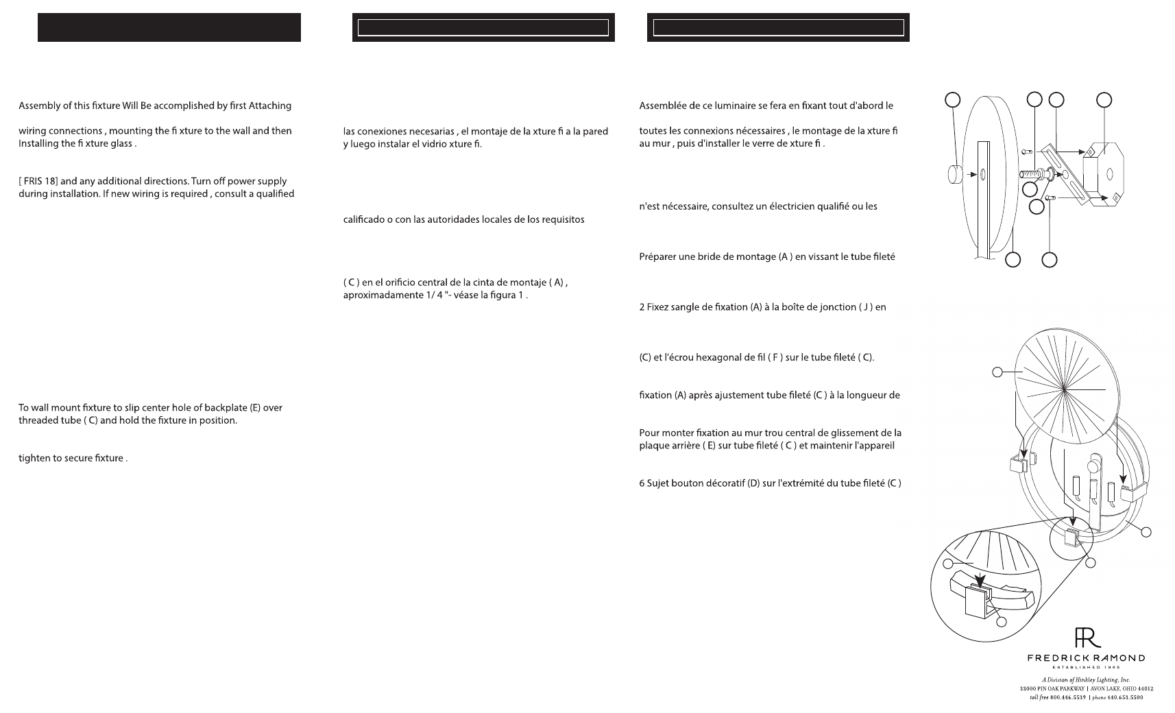
1 Prepare mounting strap (A ) by threading threaded tube ( C)
into the center hole of the mounting strap (A ) Approximately
1/4 " - see Drawing 1 .
2 Attach mounting strap (A) to junction box ( J ) using two short
screws (B) Provided .
3 Slip lock washer (F1) over nipple (C) and thread hex nut (F)
onto threaded tube ( C).
4 Hex nut (F) can be Tightened against mounting strap (A)
adjusting threaded tube ( C) to proper mounting length .
6 Thread decorative knob (D) onto threaded end of tube ( C) and
S TEP 2
Note: Fixture shoulds be lamped accordingly at the point before
this procédure .
1 To install glass (1) , slip glass betweens media clips ( 2 ) located
on the glass cradle ( 3 )
.
01.01.14