Hinkley, Start here, Commencez ici – Hinkley Lighting MERCER 3655HB User Manual
Page 2: Empezar aquí, Mounting instructions is19-96
start here
commencez ici
empezar aquí
Mounting Instructions IS19-96
L I G H T I N G
HINKLEY
English
Spanish
French
H I N K L E Y L I G H T I N G 33000 Pin Oak Parkway, Avon Lake, OH 44012 800.446.5539 / 440.653.5500 hinkleylighting.com
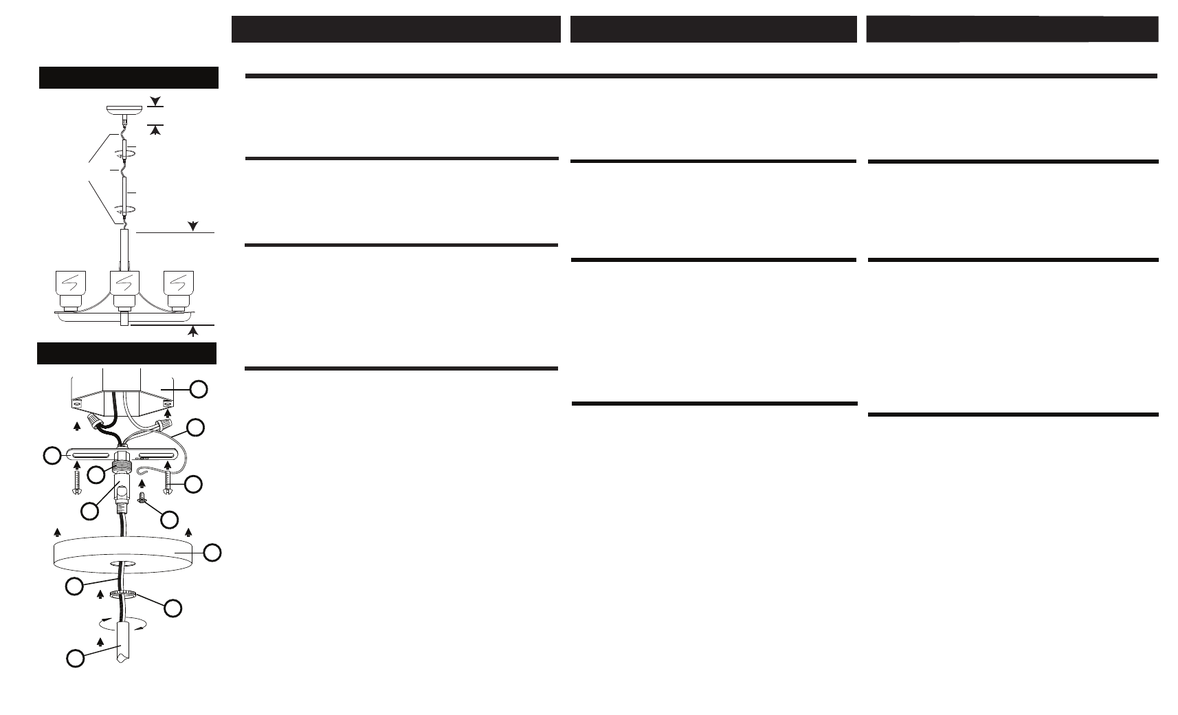
Drawing 1 - Fixture Assembly
stem
fixture supply wire
stem
Drawing 2 - Fixture Installation
SAFETY WARNING: READ WIRING AND GROUNDING INSTRUCTIONS
(I.S. 18) AND ANY ADDITIONAL DIRECTIONS. TURN POWER SUPPLY
OFF DURING INSTALLATION. IF NEW WIRING IS REQUIRED,
CONSULT A QUALIFIED ELECTRICIAN OR LOCAL AUTHORITIES FOR
CODE REQUIREMENTS.
1. Shut off electrical current before starting. If the fixture you are
replacing is turned on and off by a wall switch, simply turn the switch
off. If not, remove the appropriate fuse (or open the circut breakers)
until the fixture is dead.
• DO NOT restore current - either by fuse, breaker or switch - until
the new fixture is completely wired and in place.
1. It will be necessary to establish at what height the chandelire will be
installed at - see Drawing 1.
2. The fixture is supplied with assorted stem (S) lengths. Determine what
conbination of stem lengths will be required to achieve the height that you
have established. This is done by determining the overall height the
assembled fixture has to be, subtracting the height of the chandelier body
and the canopy asembly. The remaining length is the stem length required.
Use various combinations of stem length supplied to achieve this length.
3. Slip stems along fixture supply wire (W) and thread together until stem
length is achieved.
canopy
height
chandelier
height
H
L
S
A
B
C
G
E
F
D
W
1. In the following order : take retainer ring (L) , canopy (H) and slide them
over the stems attached previously - see Drawing 2.
2. Thread fixture supply wires (W) through center of swivel (E) that is
attached to mounting strap (A).
3. Slide swivel with mounting strap along wire and thread end of swivel
into top of stems (S).
4. Lift fixture and attach mounting strap (A) to junction box (C) using two
8/32 screws (B) (NOT PROVIDED).
5. Make all necessary electrical connections following instruction sheet
(IS-18) provided. Ground wire (D) can be attached to mounting strap (A)
using green ground screw (G).
6. Slip canopy (H) up along stems (S) and over mounting strap with swivel
and hold in position.
7. Slip retainer ring (I) up to canopy and thread onto coupler (F), to secure
canopy.
8. Return to fixture assembly instructions to complete fixture construciton.
ADVERTENCIA DE SEGURIDAD: INSTRUCCIONES DE
CABELEADO Y CONEXIÓN A TIERRA LEA (I.S. 18), E
INSTRUCCIONESADICIONALES. CORTAR EL SUMINISTRO
ELÉCTRICO DURANTE LA INSTALACIÓN. SI NUEVO CABLEADO
SE REQUIERE, CONSULTE CON UN AUTORIDADES LOCALES
PARA REQUISITOS DEL CÓDIGO.
AVERTISSEMENT DE SÉCURITÉ: LIRE RACCORDEMENT ET MISE
À LA TERRE (I.S. 18) ET TOUTE AUTRE INSTRUCTION. COUPER
L'ALIMENTATION ÉLECTRIQUE EN COURS D'INSTALLATION. SI
DE NOUVELLES CÂBLAGE N'EST NÉCESSAIRE, CONSULTEZ
UN ÉLECTRICIEN QUALIFIÉ OU LES AUTORITÉS LOCALES
POUR LES EXIGENCES DE CODE.
Instrucciones de montaje IS19-96
Instructions de montage IS19-96
1. Apague la corriente eléctrica antes de comenzar. Si el
aparato está sustitución se enciende y apaga por un interruptor
de pared, simplemente gire el interruptor
off. Si no es así, quite el fusible apropiado (o abra los
interruptores circut) hasta que el aparato esté muerto.
• NO restaurar actual - ya sea mediante fusible, disyuntor o
interruptor - hasta el nuevo dispositivo está completamente
cableada y en su lugar.
1. Couper le courant électrique avant de commencer. Si
l'appareil que vous êtes remplacement est activé et désactivé
par un interrupteur mural, il suffit de tourner l'interrupteur
off. Sinon, retirez le fusible approprié (ou ouvrez les disjoncteurs
de circuits, ou les) jusqu'à ce que l'appareil est mort.
• NE PAS restaurer actuel - soit par fusible, disjoncteur ou
interrupteur - jusqu'à le nouvel appareil est entièrement câblé
et en place.
1. Será necesario establecer a qué altura del chandelire será
instalado en - ver dibujo 1.
2. El aparato se suministra con el vástago surtidos (S) longitudes.
determinar qué Se requerirá conbination de longitudes de vástago
para alcanzar la altura que han establecido. Esto se realiza
mediante la determinación de la altura total de la accesorio montado
tiene que ser, restando la altura del cuerpo de araña y la asembly
dosel. La longitud restante es la longitud del vástago requerida.
Utilice varias combinaciones de la longitud del tallo suministrados
para lograr esta longitud.
3. Slip deriva a lo largo de cable de suministro de luminaria (W) y
el hilo juntos hasta tallo se logra longitud.
1. Il sera nécessaire d'établir à quelle hauteur la chandelire sera
installé au - voir schéma 1.
2. L'appareil est livré avec un assortiment de longueurs tige (S).
déterminer ce qui conbination de longueurs de tiges sera nécessaire
pour obtenir la hauteur que vous ont mis en place. Ceci est fait en
déterminant la hauteur totale de la appareil assemblé doit être, en
soustrayant la hauteur du corps de lustre et la asembly de la canopée.
La longueur restante est la longueur de tige nécessaire. Utiliser
diverses combinaisons de longueur de la tige fournis pour réaliser
cette longueur.
3. Glissement le long des tiges de fil d'alimentation du luminaire (W)
et le fil ensemble jusqu'à ce que la tige
longueur est atteinte.
1 En el siguiente orden:. Tener el anillo de retención (L), canopy
(H) y deslizarlos el pedúnculo adherido anteriormente - ver dibujo 2.
2. Cables de alimentación accesorio de rosca (W) a través de centro
del eslabón giratorio (E) es unido a una brida de montaje (A).
3. Deslice giratoria con estribo de montaje a lo largo de alambre e
hilo final del eslabón giratorio en la parte superior de los tallos (S).
4. Levante luminaria y fije la correa de montaje (A) a la caja de
conexiones (C) utilizando dos 8/32 tornillos (B) (no incluido).
5. Haga todas las conexiones eléctricas necesarias siguiente hoja
de instrucciones (IS-18), siempre. Cable a tierra (D) se puede
conectar a una brida de montaje (A) usando el tornillo verde de
tierra (G).
6. Deslice el dosel (H) los tallos a lo largo de (S) y la correa sobre
el montaje con el eslabón giratorio y mantenga en su posición.
7. Deslice el anillo de retención (I) hasta el dosel y enrosque en el
acoplador (F), para asegurar dosel.
8. Vuelva al accesorio instrucciones de montaje para completar
construciton accesorio.
1 Dans l'ordre suivant:. Prendre l'anneau de retenue (L), voile (H) et
glissez-les sur les tiges fixé précédemment - voir schéma 2.
2. Fils Fil appareil d'alimentation (W) à travers le centre de pivot (E)
qui est fixé à une attache de montage (A).
3. Faites glisser pivotant avec sangle de fixation le long du fil et du fil
fin de pivot en haut des tiges (S).
4. Soulevez appareil et fixer la sangle de fixation (A) à la boîte de
jonction (C) à l'aide de deux 8/32 vis (B) (non fourni).
5. Effectuer toutes les connexions électriques nécessaires suivant la
feuille d'instruction (IS-18) fourni. Le fil de terre (D) peut être fixé à la
sangle de fixation (A) aide de la vis de terre verte (G).
6. Glissez verrière (H) le long des tiges (S) et sangle de fixation
sur émerillon et maintenir en position.
7. Glissez l'anneau de retenue (I) jusqu'à la canopée et les enfiler
sur des coupleur (F), pour garantir la canopée.
8. Revenir au montage des instructions d'assemblage pour compléter
appareil construciton.