Start here, Commencez ici, Empezar aquí – Hinkley Lighting GATSBY 4933PL User Manual
Page 2: I.s. 19-95, Hanging instructions
H I N K L E Y L I G H T I N G 33000 Pin Oak Parkway Avon Lake, OH 44012 800.446.5539 / 440.653.5500 hinkleylighting.com
I.S. 19-95
hanging instructions
start here
SAFTEY WARNING: READ WIRING AND GROUND INSTRUIONS (I.S.18)
AND ANY ADDITIONAL DIRECTIONS. TURN POWER SUPPLY OFF
DURING INSTALLATION. IF NEW WIRING IS REQUIRED, CONSULT A
QUALIFIED ELECTRICIAN OR LOCAL AUTHORITIES FOR CODE
REQUIREMENTS.
1. Shut off electrical current before starting. If the fixture you are
replacing is turned on and off by a wall switch, simply turn the
switch off. If not, remove the appropriate fuse (or open the circuit
breakers) until the fixture is dead.
• DO NOT restore current – either by fuse, breaker or switch – until the
new fixture is completely wired and in place.
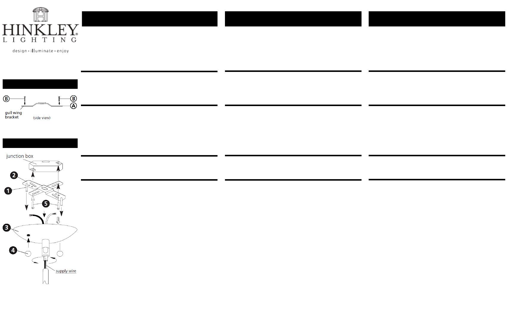
1. Slip canopy assembly (3) with swivel along wire and thread onto top
of rods that are attached to fixture – see Drawing 2.
1. Prepare mounting strap (A) by threading the two long mounting
screws (B) into the back of the gull wing bracket – see Drawing 1.
• Be sure the holes into which the screws are threaded match the
spacing of holes (D) in the backplate (E) – see Drawing 1 & 2.
2. Attach mounting strap (A) to junction box (J) using two screws (C).
3. Make wire connections following the instructions on (I.S. 18)
instruction sheet provided.
4. Slip holes in canopy (3) over screws (1) and secure fixture with ball
knobs (4).
I.S. 19-95
hanging instructions
commencez ici
AVERTISSEMENT DE SECURITE: LIRE CABLAGE ET INSTRUCTIONS DE
MISE (I.S.18), ET TOUTE AUTRE INSTRUCTION. COUPER
L’ALIMENTATION ELECTRIQUE PENDANT L’ONSTALLATION. SI DE
NOUVELLES CABLAGE N’EST NECESSAIRE, CONSULTEZ UN
ELECTRICIEN QUALIFIE OU AUTORITES LOCALES POUR EXIGENCES DU
CODE.
1. Couper le courant électrque acant de commencer. Si l’appareil vous
remplacez est activé et désactivé par un interrupteur mural, il suffit
de tourner l’interrupteur. Sinon, retirez le fusible approprié (ou
ouvrez les disjoncteurs) jusqu’à ce que l’appareil est mort.
• NE PAS restaurer actuel – soit par fusible, disjoncteur ou
interrupteur – jusqu’à ce que le nouvel appareil est entièrement
cable et en place.
1. Glissez assemblage de voilure (3) avec le pivot le long du fil et du fil
et du fil sur le dessus de tiges qui sont attachés au montage - Voir
Schéma 2.
1. Préparer sangle de fixation (A) en vissant les deux vis longues (B) à
l’arrière de la console aile de mouette – Voir Schéma 1.
• Assurez-vous que les trous dans lesquels les vis sont vissées
correspondent à l’espacement des trous (D) dans la plaque arrière
(E) – Voir Schéma 1 & 2.
2. Attacher sangle de montage (A) de la boîte de jonction (J) à l’aide
de deux vis (C).
3. Faites les brachements en suivant les instructions sur (I.S. 18) fuille
d’instructions fournies.
4. Glissez les trou dans la canipée (3) sur les vis (1) et fixation sécurisée
avec des boutons de balle (4).
I.S. 19-95
hanging instructions
empezar aquí
ADVERTENCIA DE SEGURIDAD: LE LAS INSTRUCCIONES DE
CABLEADO Y LA TIERRA (I.S.18), E INSTRUCCIONES ADICIONALES.
APAUGE LA ALIMENTACIÓN DE CORRIENTE DURANTE LA
INSTALACIÓN. SI SE REQUIERE NUEVO CABLEADO, CONSULTE CON
UN ELECTRICISTA O AUTHORIDADES LOCALES PARA REQUISTOS
DEL CÓDIGO.
1. Apague la corriente eléctrica antes de comenzar. Si el aparato va a
sustituir se enciende y se apage por un interruptor de pared,
simplemente gire el interruptor. Si no es así, quite el fusible
adecuado (o abra los interruptores de circuito) hasta que el
aparato está muerto.
• NO restaurar actual – ya sea mediante fusible, disyuntor o
interruptor – hasta que el Nuevo dispositivo está completamente
conectado y en su lugar.
1. Deslice conjunto de cubierta (3) con el eslabón giratorio lo largo
del alambre e hilo en la parte superior de las barras que se unen al
dispositivo - Véase la Figura 2.
1. Preparar cinta de montaje (A), enroscando los dos tornillos de
montaje largos (B) en la parte posterior del soporte de ala de gaviota
- Véase la Figura 1.
• Asegúrese de que los agujeros en los que se enroscan los tornillos
coincidan con el espaciamiento de los agujeros (D) en la placa trasera
(E) – Véase la Figura 1 & 2.
2. Sujete la correa de montaje (A) a la caja de conexiones (J) con dos
tornillos (C).
3. Hag alas conexiones de cables siguiendo las Instrucciones que
aparecen en (I.S. 18)
4. Deslice los agujeros en canopy (3) sobre los tornillos (1) y el accesorio
seguro con perillas de bolas (4).
Drawing 1 – Strap Detail
Drawing 2 – Mounting Instructions