Hinkley Lighting CLAYTON 2435 User Manual
Start here, Commencez ici, Empezar aquí
H I N K L E Y L I G H T I N G 33000 Pin Oak Parkway Avon Lake, OH 44012 800.446.5539 / 440.653.5500 hinkleylighting.com
Assembly Instructions
Item No. 2430/2434/2435
start here
1. Find a clear area in which you can work.
2. Unpack fixture from carton.
3. Carefully review instructions prior to assembly.
*** The construction of this fixture will be accomplished by first
installing mounting hardware, making all necessary electrical
connections, mounting fixture to wall, installing the mirror and candle
sleeves, installing the glass, and then attaching the door.
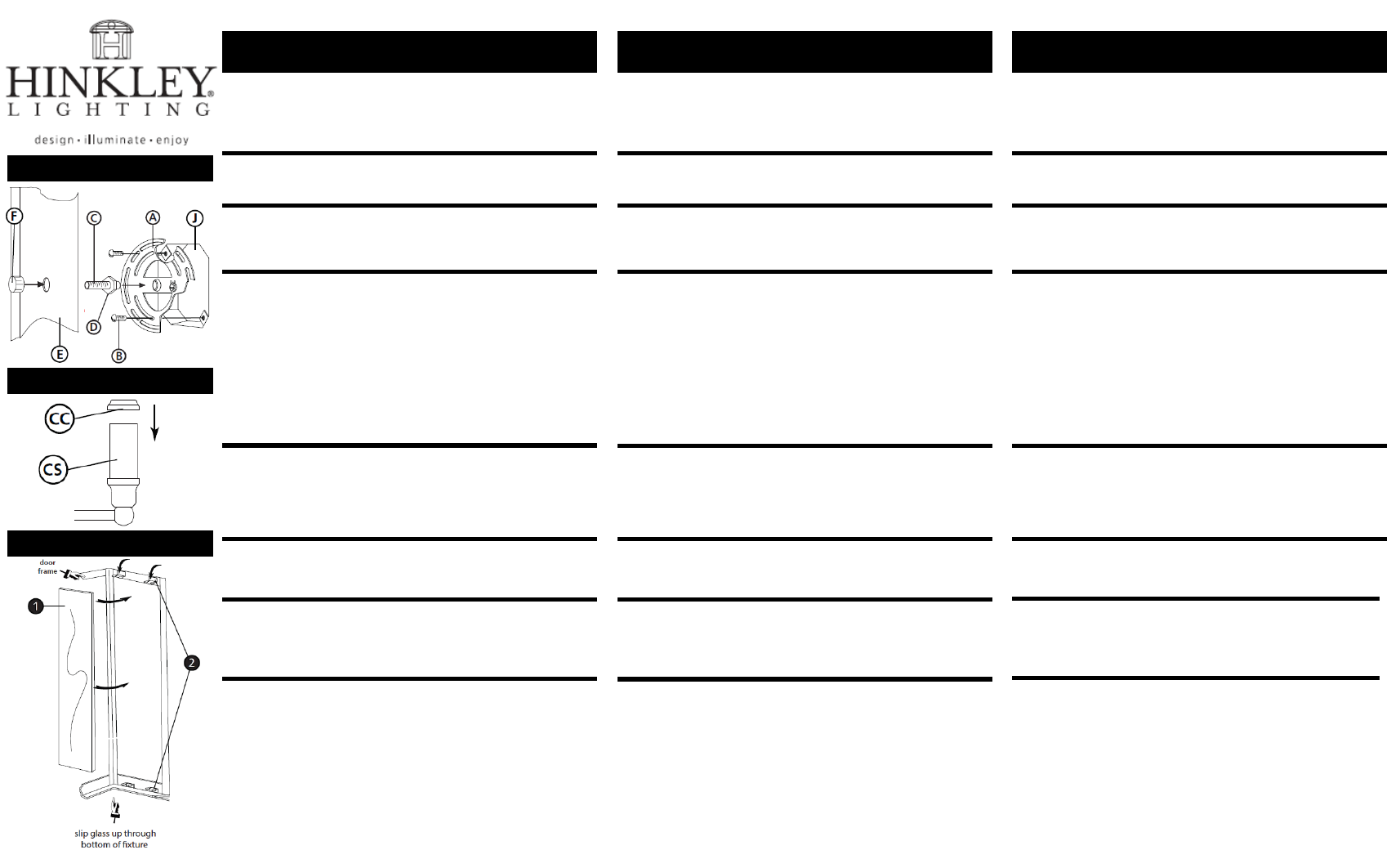
1. Prepare threaded tube (C) by threading on hex nut (D) approximately ½”.
2. Thread tube (C) in mounting strap (A), approximately ¼” – see Drawing 2.
3. Attach mounting strap (A) to junction box (J) using two screws (B) provided.
4. It will be necessary to adjust threaded tube (C). This is done by slipping the
mounting hole (E) over threaded tube (C) and holding the fixture against the
wall. Adjust threaded tube (C) until there is approximately 3/8” of thread
showing inside the fixture. Remove fixture from wall and tighten hex nut (D)
against mounting bracket (A) to secure threaded tube (C) in place.
SAFTEY WARNING: READ WIRING AND GROUND INSTRUIONS (I.S.18)
AND ANY ADDITIONAL DIRECTIONS. TURN POWER SUPPLY OFF
DURING INSTALLATION. IF NEW WIRING IS REQUIRED, CONSULT A
QUALIFIED ELECTRICIAN OR LOCAL AUTHORITIES FOR CODE
REQUIREMENTS.
Make electrical connections from supply wire to fixture lead wires. Refer to
instruction sheet (I.S. 18) and follow all instructions to make all necessary
wiring connections.
1. To mount fixture, slip center hole of backplate (E) over nipple (C) and hold
fixture in position – see Drawing 1.
2. Thread decorative knob (F) onto end of nipple (C) and tighten to secure
fixture.
1. After mounting fixture to wall, install the side panels of glass (1) by sliding
them through the bottom frame, and placing them between the glass clips (2)
and against the fixture frame – see Drawing 3.
2. Fold glass clips (2) up against glass to secure glass in fixture.
3. Now insert the curved front panel (not shown) into bottom of fixture and
install in shame fashion as the side panels.
Les Instructions D’assemblage
Numéro d’article: 2430/2434/2435
commencez ici
1. Trouvez un espave libre dans lequel vous pouvez travailler.
2. Déballlez appareil de la boîte.
3. Examinez attentivement les instructions avant le montage.
*** La construction de ce dispositif sera réalisé selon la première de
montage de la bride de montage de la boîte de jonction, toutes les
connexions électriques nécessaires, le montage de la fixation à la
paroi, lamping le projecteur, puis l’installation du verre.
1. Préparer tube fileté (C) en vissant l’écrou hexagonal (D) d’eviron 12.7 mm.
2. Tube de threads (C) en sangle de fixation (A), soit environ 6.35 mm – Voir
Schéma 2.
3. Attacher la sangle de fixation (A) à la boîte de jonction (J) à l’aide de deux vis
(B) fournies.
4. ll sera nécessaire d’ajuster tube fileté (C). Cela se fait en glissant le trou de
montage (E) sur tube fileté (C) et en maintenant la fixation contre le mur.
Régler le tube fileté (C) jusqu’à ce qu’il y est d’environ 9.525 mm de fil
montrant l’intérieur de l’appareil. Retirer projecteur du mur et serrez l’écrou
hexagonal (D) contre le support de montage (A) pour fixer le tube fileté (C)
en place.
AVERTISSEMENT DE SECURITE: LIRE CABLAGE ET INSTRUCTIONS DE
MISE (I.S.18), ET TOUTE AUTRE INSTRUCTION. COUPER
L’ALIMENTATION ELECTRIQUE PENDANT L’INSTALLATION. SI DE
NOUVELLES CABLAGE N’EST NECESSAIRE, CONSULTEZ UN
ELECTRICIEN QUALIFIE OU AUTORITES LOCALES POUR EXIGENCES DU
CODE.
Effectuez les connexions électriques du cable d’alimentation à fils de
connexion du projecteur. Reportez-vous à la feuille d’instruction (I.S. 18) et
suivez toutes les instructions pour effectuer tous les branchements nécessaires.
1. Pour monter appareil, glisser le trou central de la plaque arrière (E) dessus du
mamelon (C) et tenir l’appareil en position – Voir Schéma 1.
2. Discussion bouton decorative (F) sur l’extrémité de mamelon (C) et serrer pour
sécuriser appareil.
1. Après fixation de montage au mur, installer les panneaux latéraux de la vitre
(1) en les glissant à travers la trame de fond, et en les plaçant entre les pinces
de verre (2) et contre le châssis de fixation – Voir Schéma 3.
2. Clips de verre de pliage (2) vers le haut contre le verre pour fixer le verre à
luminaire.
3. Maintenant, insérez le panneau avant incurve (non représenté) dans le bas du
luminaire et installer en mode de honte que les panneaux latéraux.
Instrucciones De Montaje
Número del artículo: 2430/2434/2435
empezar aquí
1. Busque un lugar claro en el que se puede trabajar.
2. Desembale accesorio de la caja.
3. Revise cuidadosamente la Instrucciones antes del montaje.
*** La construcción de este dispositivo se logra mediante el montaje de
la primera correa de montaje a la caja de conexiones, por lo que todas
las conexiones eléctricas necesarias, el accesorio de montaje a la pared,
el dispositivo de cambio de la lámpara, y luego instalar el cristal.
1. Prepare tubo roscado (C), enroscando la tuerca hexagonal (D) de
aproximadamente 12.7mm.
2. Tubo de rosca (C) en la brida de montaje (A), aproximadament 6.35mm –
Véase la Figura 2.
3. Sujete la correa de montje (A) a la caja de conexiones (J) con dos tornillos
(B) suministrados.
4. Será necesario ajustar tubo roscado (C). Esto se realize mediante el
deslizamiento del orificio de montaje (E) sobre el tubo roscado (C) hasta que
quede aproximadament 9.525 mm de hilo mostrando el interior del aparato.
Retire aparato de la pared y apriete la tuerca hexagonal (D) contra el
soporte de montaje (A) para fijar tubo roscado (C) en su lugar.
ADVERTENCIA DE SEGURIDAD: LE LAS INSTRUCCIONES DE
CABLEADO Y LA TIERRA (I.S.18), E INSTRUCCIONES ADICIONALES.
APAUGE LA ALIMENTACIÓN DE CORRIENTE DURANTE LA
INSTALACIÓN. SI SE REQUIERE NUEVO CABLEADO, CONSULTE CON
UN ELECTRICISTA O AUTHORIDADES LOCALES PARA REQUISTOS
DEL CÓDIGO.
Effectuez les connexions électriques du cable d’alimentation à fils de
connexion du projecteur. Reportez-vous à la feuille d’instruction (I.S. 18) et
suivez toutes les instructions pour effectuer tous les branchements
nécessaires.
1. Para montar aparato, deslice el orificio central del disco (E) en la boquilla (C)
y mantenga fijo en la posición – Véase la Figura 1.
2. Tema botón decorativo (F) en el extreme del pezón (C) y apriete para
asegurar accesorio.
1. Después de acesorio de montaje a la pared, instalar los paneles laterals de
vidrio (1) por delizamiento a través del marco inferior, y colocarlos entre los
cierres de cristal (2) y contra el marco de accesorio – Véase la Figura 3.
2. Clips de cristal plegable (2) en contra de vidrio para asegurar vidrio accesorio.
3. Ahora inserter el panel frontal curvada (no mostrada) en la parrte inferior
de la fijación e instalar en la moda pena, ya que los paneles laterals.
Drawing 1 – Fixture Mounting
Drawing 2 – Fixture Assembly
Drawing 2 – Fixture Assembly