U-gage, S18u series sensor — analog output, Teaching minimum and maximum limits – Banner U-GAGE S18U Series—Analog User Manual
Page 4: Analog output slope
U-GAGE
™
S18U Series Sensor — Analog Output
4
P/N 110738 rev. A
Banner Engineering Corp.
•
Minneapolis, MN U.S.A.
www.bannerengineering.com • Tel: 763.544.3164
4
Near
Window
Far
Window
20
Target Position
Analog Output (mA)
Positive
Slope
Current-Sourcing Models
Teaching Minimum and Maximum Limits
General Notes on Programming
• The sensor will return to Run mode if the first Teach condition is not registered
within 120 seconds.
• After the first limit is taught, the sensor will remain in Program mode until the Teach
sequence is finished.
• To exit Program mode without saving any changes, press and hold the programming
push button > 2 seconds (before teaching the second limit). The sensor will revert to
the last saved limits.
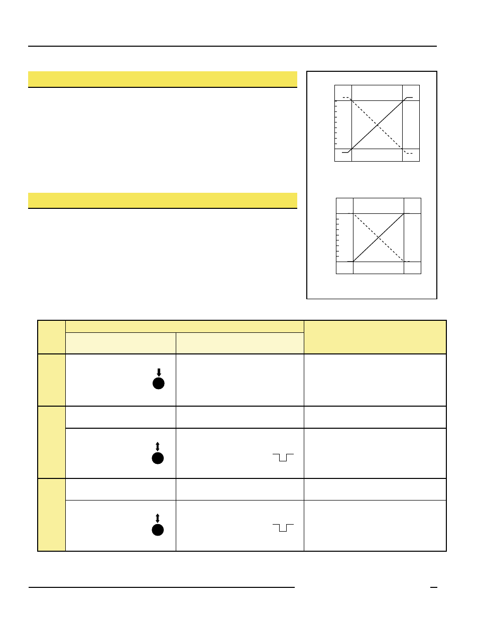
Analog Output Slope:
The U-GAGE S18U sensor may be programmed for either a positive or a negative
output slope, based on which limit is taught first (see Figure 3). If the Near limit is
taught first, the slope will be positive. If the Far limit is taught first, the slope will be
negative. Banner’s scalable output automatically distributes the output signal over the
width of the programmed sensing window.
In the event of signal loss, the analog output goes to 3.6 mA or 0V dc, which may be
used to trigger an alarm.
0
Near
Window
Far
Window
10
Target Position
Analog Output (V dc)
Positive
Slope
Voltage-Sourcing Models
Figure 3. Analog output slope
Procedure
Result
Push Button
0.04 < “click” < 0.8 sec.
Remote Wire
0.04 sec. < T < 0.8 sec.
Programming
Mode
• Push and hold the
push button
• No action required; sensor is ready for
1st limit teach
Output LED: ON Red
Power LED: ON Green (good signal) or
ON Red (no signal)
Teach
First
Limit
• Position the target for
the first limit
• Position the target for the first limit
Power LED: Must be ON Green
• “Click” the push button
• Single-pulse the remote line
Teach Accepted
(Sensor learns the 0V dc or 4 mA limit)
Output LED: Flashing Red
Teach Unacceptable
Output LED: ON Red
Teach
Second
Limit
• Position the target for
the second limit
• Position the target for the second limit
Power LED: Must be ON Green
• “Click” the push button
• Single-pulse the remote line
Teach Accepted
(Sensor learns the 10V dc or 20 mA limit)
Output LED: Yellow or OFF
Teach Unacceptable
Output LED: Flashing Red
T
T
T
T
T
T
T
T
T
T
T
T
T
T
T
T
T
T
T
T
T
T
T
T
T
T
T
T
T
T
T
T
T
T
T
T
T
T
T
T
...
...
D
or
...
...
D
or
...
...
D
or
B