U-gage, S18u series sensor — analog output, Sensor programming – Banner U-GAGE S18U Series—Analog User Manual
Page 3: Status indicators
P/N 110738 rev. A
3
U-GAGE
™
S18U Series Sensor — Analog Output
Banner Engineering Corp.
•
Minneapolis, MN U.S.A.
www.bannerengineering.com • Tel: 763.544.3164
Sensor Programming
Two TEACH methods may be used to program the sensor:
• Teach individual minimum and maximum limits, or
• Use Auto-Window feature to center a sensing window around the taught position.
The sensor may be programmed either via its push button, or via a remote switch.
Remote programming also may be used to disable the push button, preventing
unauthorized personnel from adjusting the programming settings. To access this
feature, connect the gray wire of the sensor to 0 - 2V dc, with a remote programming
switch between the sensor and the voltage.
NOTE: The impedance of the Remote Teach input is 12 kΩ.
Programming is accomplished by following the sequence of input pulses (see
programming procedures starting on page 4). The duration of each pulse
(corresponding to a push button “click”), and the period between multiple pulses, are
defined as “T”:
0.04 seconds < T < 0.8 seconds
Power/
Signal Strength
LED
TEACH/
Output Indicator
LED
TEACH
Push Button
PWR
OUT
TEACH
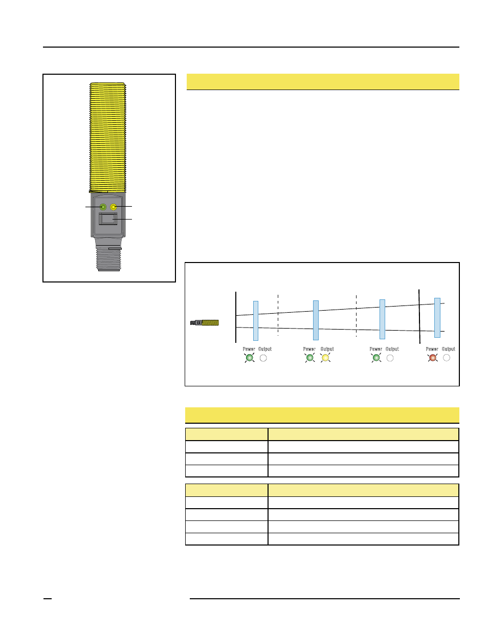
Figure 1. Sensor features
Minimum
Operating
Range
Near
Setpoint
Far
Setpoint
Maximum
Operating
Range
Ta
rget
Ta
rget
Ta
rget
Ta
rget
Dead Zone
Output
Power
Output
Power
Output
Power
ON:
Green
OFF
Output
Power
OFF
ON:
Green
ON:
Yellow
ON:
Green
OFF
ON:
Red
OFF
Figure 2. TEACH Interface
Status Indicators
Power ON/OFF LED
Indicates
OFF
Power is OFF.
ON Red
Target is weak or outside sensing range.
ON Green
Sensor is operating normally, good target.
Output/Teach LED
Indicates
OFF
Target is outside window limits.
Yellow
Target is within window limits.
ON Red (solid)
In Teach Mode, waiting for first limit.
ON Red (flashing)
In Teach Mode, waiting for second limit.
B