Wiring connections, Specifications for q45 namur sensors – Banner Q45 Namur DC Series User Manual
Page 5
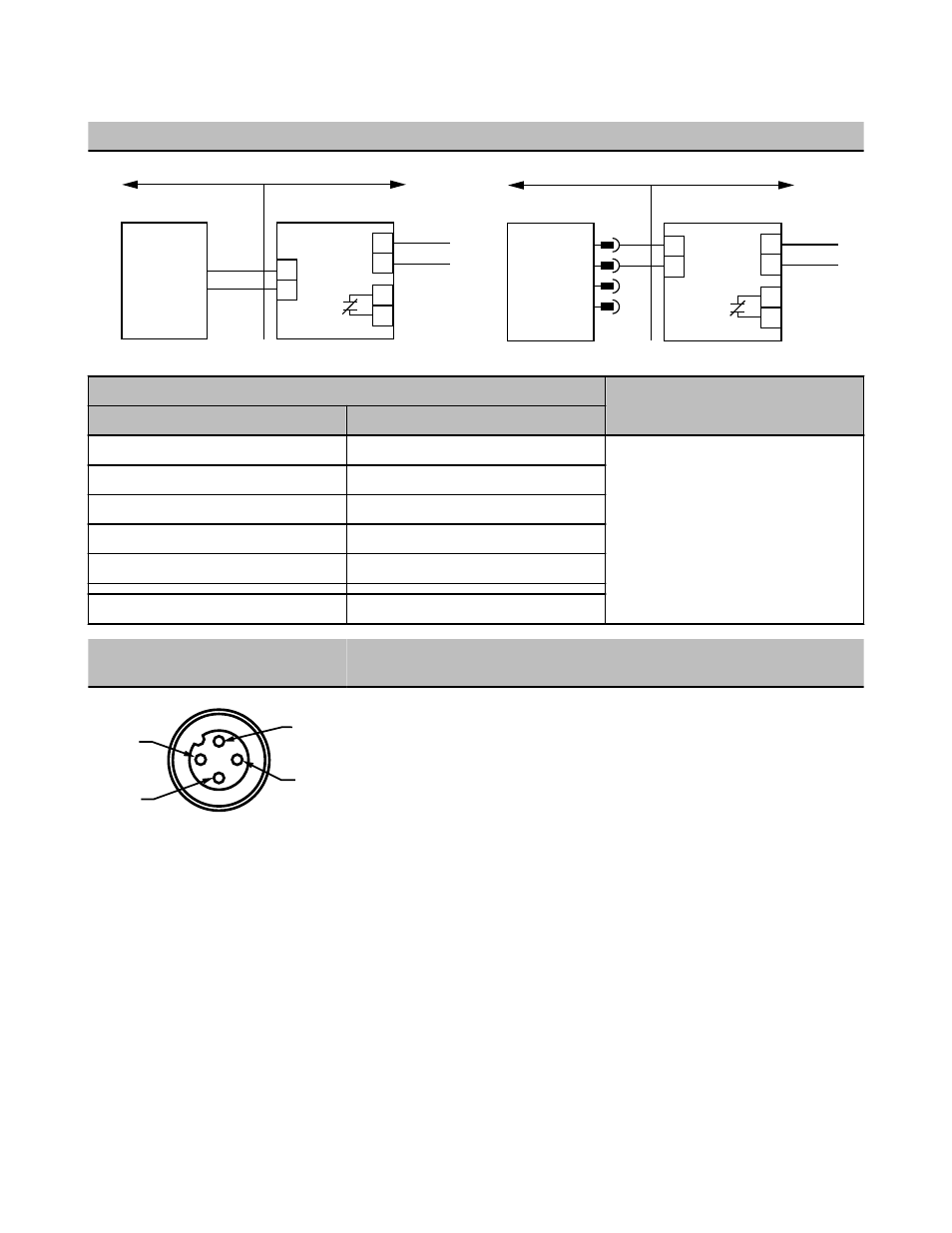
Wiring Connections
NAMUR Sensors with Attached Cable
NAMUR Sensors with Quick-Disconnect
NAMUR Sensor
Hazardous Area
≤ 15V dc
Power
Output
Sensor
Input
Non-hazardous Area
Associated Apparatus
br
bu
+
–
+
–
NAMUR Sensor
Hazardous Area
1
≤ 15V dc
Power
Output
Sensor
Input
Non-hazardous Area
Associated Apparatus
2
br
bu
3
4
+
–
+
–
Entity Parameters
HAZARDOUS AREA APPLICATION
Associated Apparatus
Sensor Apparatus
Voc ≤ 15V dc
Vmax = 15V dc
“Associated apparatus” may include intrinsi-
cally safe amplifiers and barriers to monitor
sensor supply current, which is the sensor’s
output signal. Associated apparatus must
limit both supply voltage and supply current
in the event of failure.
Isc ≤ 60 mA
Imax = 60 mA
Ca ≤ *C (cable) + Ci
Ci = 0.3 µF
La ≤ *L (cable) + Li
Li = 0
Pi = 225 mW
*C(cable) = 60 pF/ft
*L(cable) = 0.2 μH/ft
4-pin Euro-style Pinout (Cable Connec-
tor Shown)
No.
Wire Color
2
3
4
1
1
Brown
2
Blue
3
N/A
4
N/A
Specifications for Q45 NAMUR Sensors
Supply Voltage and Current
5 to 15V dc. Supply voltage is provided by the amplifier
to which the sensor is connected.
Adjustments
Multi-turn sensitivity control on top of sensor, beneath a
transparent o-ring sealed cover, allows precise sensi-
tivity setting (turn clockwise to increase gain).
Indicators
Indicator LEDs are highly visible, located beneath a
raised transparent dome on top of the sensor.
POWER (red) LED (emitters only) lights whenever 5–
15V dc power is applied
Output
Constant current output: ≤ 1.2 mA in the “dark” condi-
tion and ≥ 2.1 mA in the “light” condition
Output Response Time
Opposed mode receiver: 2 milliseconds on/0.4 millisec-
onds off. All others 5 milliseconds on/off (does not in-
clude amplifier response)
Environmental Rating
NEMA 6P, IEC IP67
Operating Conditions
Temperature: –40° to +70 °C (–40 to +158 °F)
Q45 NAMUR Sensors
P/N 038343 Rev. H
www.bannerengineering.com - tel: 763-544-3164
5