L-gage q50a, Analog output sensor – Banner L-GAGE Q50 Series—Analog User Manual
Page 4
L-GAGE Q50A –
Analog Output Sensor
page
4
Teaching Analog Limits Using a Fixed 50 mm Window
For some analog applications, a fixed sensing window centered about a taught point is
required. The TEACH procedure is simple: teaching the same limit twice causes the
sensor to program a window centered on the position taught. This window is 50 mm
wide (taught position ± 25 mm).
Remote Programming
A function is provided to program the sensor remotely or to disable/enable the push
button; this is accomplished via the gray wire. Disabling the push button prevents
anyone on the production floor from adjusting any of the programming settings.
Connect the gray wire of the Q50A Gauging Sensor to +5 to 30V dc, with a remote
programming switch connected between them. NOTE: The impedance of the remote
teach input is 15 k
Ω
.
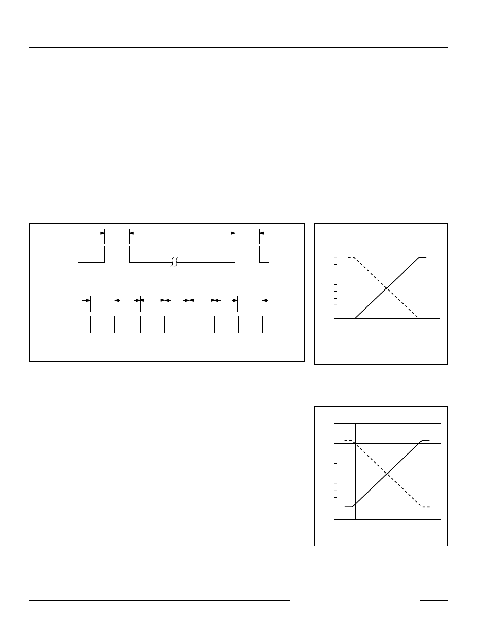
To program, pulse the wire as illustrated in Figure 5. NOTE: The duration of each pulse
(corresponding to a push button “click”) is 0.04 to 0.8 seconds.
Teach First
Window Limit
Remote Teach
Window Limits
Teach Second
Window Limit
Push Button Lockout
Push Button
Lockout
T
> 0.8 sec
T
T
T
T
T
T
T
T
0.04 sec < T < 0.8 sec
Figure 5. Timing for remote TEACH programming
Run Mode
NOTE: All LED indicators momentarily go OFF when the sensor changes state between
RUN and TEACH modes.
Range LED
When the sensor detects a target within its sensing range (either 50 to 150 mm for
visible-beam models, or 50 to 200 mm for infrared beam models) the LED will be solid
green. In the absence of a target, the Range LED is solid red. Refer to the Indicator
Status table on page 3.
Teach/Output LED
In RUN mode, the Output LED is yellow when a target is sensed within the
programmed window limits; otherwise the Output LED is red. Refer to the Indicator
Status table on page 3.
Analog Output
The Q50A gauging sensor may be programmed for either a positive or a negative output
slope (see Figure 6). If the near limit is taught first, the slope will be positive; if the far limit
is taught first, the slope will be negative. Banner’s patented scalable analog output
automatically distributes the output signal over the width of the programmed sensing
window. (Output is either 0 to 10V or 4 to 20 mA, depending on model.)
0
Near
Window
Far
Window
10
Target Position
Analog Output (V dc)
Positive
Slope
Figure 6. Analog voltage output as a
function of target position
(loss of signal – 0 Volts)
4
Near
Window
Far
Window
20
Target Position
Analog Output (mA)
Positive
Slope
Figure 7. Analog current output as a
function of target position
(loss of signal – 3.6 mA)
Banner Engineering Corp.
•
Minneapolis, U.S.A.
www.bannerengineering.com • Tel: 763.544.3164