Two-point static teach (switch point), Two-point teach and manual adjust – Banner FI22 Expert Series User Manual
Page 4
FI22FP Low-Profile Inline Plastic Fiber Optic Sensor
4
P/N 108899 rev. C
Banner Engineering Corp.
•
Minneapolis, MN U.S.A.
www.bannerengineering.com • Tel: 763.544.3164
Sensor positions
threshold midway
between taught conditions
Sensor positions
threshold midway
between taught conditions
Darkest
(no signal)
Darkest
(no signal)
Most Light
(saturated
signal)
Most Light
(saturated
signal)
Single
taught
point
Sensing window size
adjusted by
Manual Adjust
Output OFF
Output OFF
Output OFF
Output ON
Output ON
Darkest Taught
Condition
Lightest Taught
Condition
Position
adjusted by
Manual Adjust
Darkest
(no signal)
Most Light
(saturated
signal)
Output OFF
Output ON
2nd Taught
Condition
1st Taught
Condition
Position
adjusted by
Manual Adjust
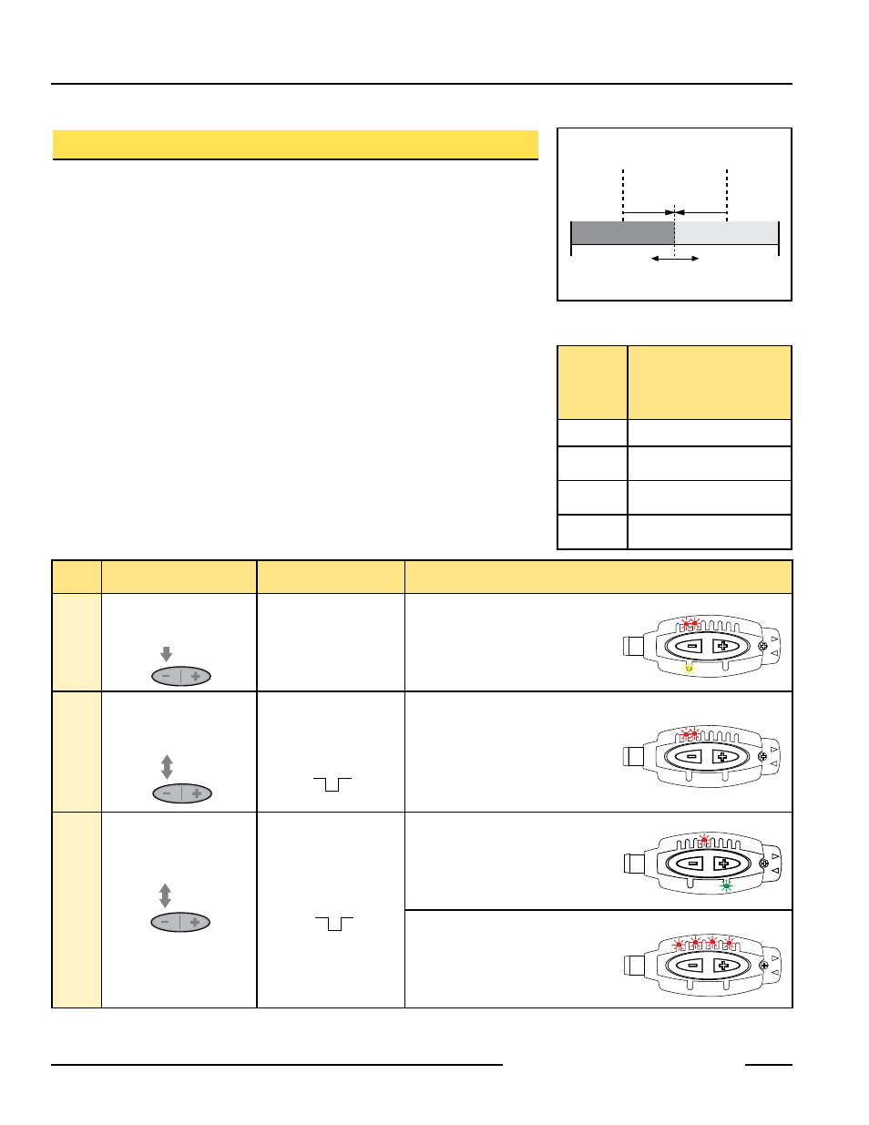
Figure 2. Two-Point TEACH (Light Operate
shown)
Two-Point Static TEACH (Switch Point)
• Sets a single switching threshold
• Threshold position is adjustable using “+” and “-” buttons (Manual Adjust)
Two-Point TEACH is the traditional setup method, used when two conditions can be
presented by the user. The sensor locates a single sensing threshold (the switch point)
midway between the two taught conditions, with the Output ON condition on one side, and
the Output OFF condition on the other (see Figure 2).
The first condition taught is the ON condition. The Output ON and OFF conditions can be
reversed by changing Light/Dark Operate status in SETUP mode.
Two-Point TEACH and Manual Adjust
Using Manual Adjust with Two-Point TEACH moves the switching threshold. The lighted
LED on the bargraph will move to exhibit the relative amount of received signal.
Push Button
0.04 sec.
≤ “click” ≤ 0.8 sec.
Remote Line
0.04 sec.
≤ T ≤ 0.8 sec.
Result
Access
TEACH
Mode
• Press and Hold
> 2 seconds
No action required;
sensor is ready for 1st
TEACH condition.
Power LED: OFF
Output LED: ON
Status LEDs: #2 & 3 Alternately flashing
Learn
Output
ON
Condition
• Present Output ON
condition
• Click push button
• Present Output ON
condition
• Single-pulse remote line
Power LED: OFF
Output LED: OFF
Status LEDs: #2 & 3 Alternately flashing
Learn
Output
OFF
Condition
• Present Output OFF
condition
• Click push button
• Present Output OFF
condition
• Single-pulse remote line
Teach Accepted
Power LED: ON
Bargraph: One LED flashes to show
relative contrast (good signal
difference shown; see table above)
Sensor returns to Run mode
Teach Unacceptable
Power LED: OFF
Bargraph: #1, 3, 5, 7 Alternately flash
to show failure
Sensor returns to “Learn Output ON”
condition
Bargraph
LED
Following
TEACH
Relative Signal Difference/
Recommendation
6 to 8
Excellent: Very stable operation
4 to 5
Good: Minor sensing variables
will not affect sensing reliability.
2 to 3
Low: Minor sensing variables
may affect sensing reliability.
1
Unreliable: Consider an
alternate sensing scheme.
T
T T T
T
T
T
T
T
T
T
T
T
T
T
T
T T T
T
T
T
T
T
T
T
T
T
T
T