Overview, Sensor programming – Banner FI22 Expert Series User Manual
Page 3
P/N 108899 rev. C
3
FI22FP Low-Profile Inline Plastic Fiber Optic Sensor
Banner Engineering Corp.
•
Minneapolis, MN U.S.A.
www.bannerengineering.com • Tel: 763.544.3164
FI22FP Low-Profile Inline Plastic Fiber Optic Sensor
Overview
The FI22FP is an easy-to-use, low-profile fiber optic sensor. It provides high-performance
sensing in low-contrast applications and its small size lets it mount almost anywhere.
Configuration options include SETUP mode plus static, dynamic and single-point TEACH-
mode programming, in addition to manual fine adjustment, remote programming and
security lockout options.
The sensor has bipolar outputs, one each NPN and PNP.
The sensor’s compact housing has a large, easy-to-see bargraph display plus bright LEDs
for easy programming and status monitoring during operation. The sensor quickly snap-
mounts to its custom bracket (included with sensor).
Sensor Programming
Sensor configuration is accomplished through TEACH-mode programming and SETUP
mode. After TEACH mode has defined the sensing parameters, SETUP mode may be used
to enable the delay or to change the light/dark operate status. Manual Adjust may be used
to fine-tune the thresholds (see page 9). Two push buttons, Dynamic (+) and Static (-), or
the remote wire, may be used to access and set programming parameters.
Sensor programming may be accomplished using any of three TEACH methods. A single
switching threshold may be programmed using either dynamic (on-the-fly) or static TEACH.
In addition, single-point static TEACH may be used to define a sensing window, centered on
a single taught condition. Single-point TEACH can be accomplished only statically.
Remote Programming
The Remote Programming function may be used to program the sensor remotely or to
disable the push buttons for security. Connect the gray wire of the sensor to ground (0V
dc), with a remote programming switch connected between them. Pulse the remote line
according to the diagrams in the programming procedures. The length of the individual
programming pulses is equal to the value T:
0.04 seconds
≤ T ≤ 0.8 seconds
Returning to RUN Mode
TEACH and SETUP modes each may be exited either after the 60-second time-out, or by
exiting the process:
• In static TEACH mode, press and hold the Static (-) button (or hold the remote line) for 2
seconds. The sensor returns to RUN mode without saving any new settings.
• In SETUP mode, press and hold both the Static (-) and Dynamic (+) buttons (or hold
the remote line) for 2 seconds. The sensor returns to RUN mode and saves the current
setting.
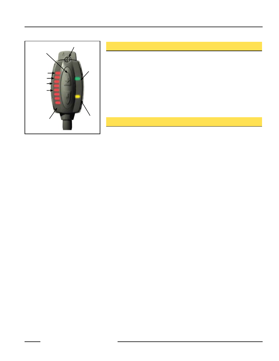
Green
Power ON
Indicator
Yellow Output
Conducting
Indicator
Programming
Push Buttons
Bargraph
Display
Delay
Dark Operate
Light
SETUP Status
Indicators:
Figure 1. FI22FP features
Fiber Ports
Switching
Point