Mini-array, Heated enclosure, Sensor mounting and alignment – Banner A-GAGE MINI-ARRAY Series User Manual
Page 6: Operation
MINI-ARRAY
™
Heated Enclosure
page
6
Sensor Mounting and Alignment
1)
Assemble the brackets supplied with the Heated Enclosure to each end of the
sensor (Figure 6), using 2 hex head screws with integral compression washer per
bracket (M4 x 10 – non QD end; M30 Nut and washer – QD end, supplied with
sensors). (Although both screws and brackets are supplied with each MINI-
ARRAY sensor, use only the brackets packed with the Heated Enclosure.)
2)
Adjust the location of the spring nuts in the rear slots to align with the holes in
the sensor mounting brackets and install the sensor using the supplied #10
hardware. Adjust the height of the sensor to match the height of the opposing
sensor; ensure that the sensor lens is oriented parallel to the enclosure window.
3)
Connect the sensor cable to the sensor’s QD connector. See the instructions
packed with each sensor for connecting the sensor cable to the array controller.
After all sensor wiring is completed, follow the instructions packed with the
sensor controller for optimizing alignment. Rotate the enclosure as needed to
align the emitter and receiver arrays.
Final Assembly
1)
Attach the second cable clip to the inside of the cover plate, as shown in
Figure 6. Assemble the cover plate to the housing using the supplied #8
hardware. Attach the heater supply cable to the cable clip on the cover plate.
2)
Connect the heater supply cable to the heated window assembly. Mount the
heated window assembly to the enclosure using the supplied #8 hardware.
3)
Connect the heater power cable to the cable from the Transformer Power Supply
(see instructions packed with Power Supply). The red LED at the top of the
heated window assembly indicates when the heater element is active.
Operation
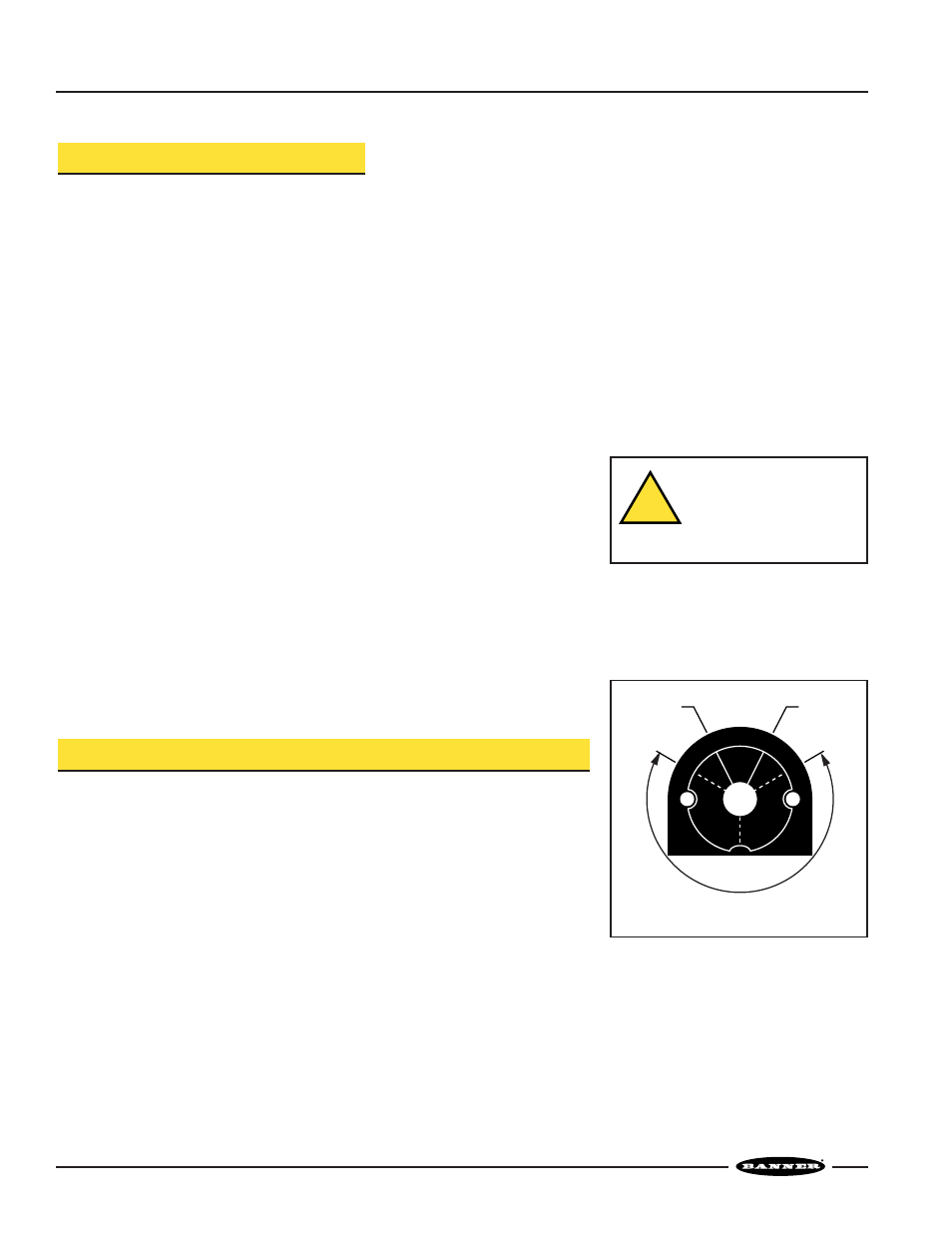
Adjusting the Humidistat
The humidistat is adjustable between 20% and 80% relative humidity; the factory
setting is 80% relative humidity, the optimal setting for most applications.
To eliminate the humidistat from the window control circuit, turn the knob fully
counter-clockwise to the OFF position. To manually close the contacts on the
humidistat, turn the knob fully clockwise, to the ON position.
For accurate operation, do not attempt to adjust the humidistat below 20% or above
80% relative humidity.
Figure 7. Humidistat control
20%
80%
50%
RE
LATI
VE HUMIDIT
Y
DO
NOT
EXCEED 80
%
DEAD
ZONE
ON
For accurate operation, do not set
humidistat below 20% or above 80%
OFF
CAUTION . . .
Do Not Touch Glass or
Window Frame When
Heating Element is ON
Glass becomes hot; a burn may result.
!