Mini-array, Heated enclosure, Installation – Banner A-GAGE MINI-ARRAY Series User Manual
Page 3: Assembly, Electrical connections
Installation
MINI-ARRAY
™
Heated Enclosure
page
3
Assembly
1)
Prepare a 6" x 6" square mounting pad, using four 3/8" studs (not included).
2)
Mount the base plate to the housing (Figure 6) with 4 stainless steel flat head
screws (1/4" - 20 x 3/4", included).
3)
Feed the heater cable and the sensor cable through the cutout in the base plate;
set the housing/base plate assembly onto the mounting pad.
4)
Level the housing in one of 2 ways:
• Using 3 user-supplied 3/8" - 24 x 2" bolts and lock nuts; or
• Using 4 leveling nuts, threaded onto the four mounting studs, under the base
plate. After leveling, secure the housing assembly using four 3/8" nuts on the
four mounting studs (Figure 3). Add flat washers and lock washers, as required
(not included).
Electrical Connections
Heater Supply Cable
Transformer Power Supplies convert 115V ac to the voltage required by the heated
window and humidistat. See Figure 6 and page 7 for more information.
1)
The heated window is powered at the top of the enclosure. Route the heater
supply cable to the top of the enclosure along one side wall. Cut off any excess
cable, leaving enough to make the connections. Secure the cable midway along
the sidewall, using one of the supplied cable clips.
2)
Strip the heater supply cable insulation as shown in Figure 4. Install the ring
terminal on the ground wire. Install the male connector pins on the 2 power
wires, using Molex crimping tool model HTR01031E, or equivalent.
3)
Push the power wires into the 2 male connector pins, and crimp. Insert the pins
into the Molex 2-pin connector (see Figure 4). Attach the ring terminal to the hole
at the upper back of the enclosure, using the supplied #10 hardware.
Humidistat Supply Cable
1)
Insert 6 spring nuts into the rear slots in the back of the enclosure, 3 on each
side. (Two nuts will be for attaching the humidistat bracket, and 4 will be for
attaching the sensor brackets, at top and bottom.) Mount the humidistat/bracket
assembly to the upper back of the enclosure.
2)
Push the 2 wires with blade terminals into place on the humidistat wiring
harness; push firmly until they “click” into place. (Connect either wire to either
terminal; polarity is not important.)
Sensor Cable
1)
Route the sensor cable terminal to the top of the enclosure, leaving enough to
bend it at the top and plug it into the sensor. If you are supplying non-Banner
cables and using the field-wireable connector, see Step 2.
2)
To install the field-wireable connector, follow the wiring connections as shown in
Figure 5. Be sure to allow enough space at the top of the Heated Enclosure when
mounting the sensors, to accommodate this connector’s additional length (as
compared with the standard Banner QD cable). See page 7 for more information
about the field-wireable connector.
NOTE: The connector pins accept up to 14 gauge stranded wire; 16 gauge
stranded wire is recommended for the sensor cable wires.
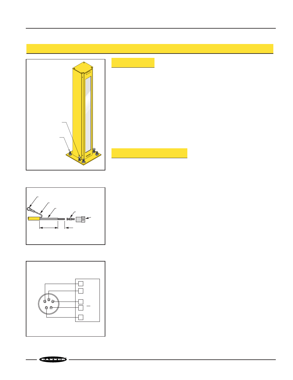
Figure 3. Base mounting and leveling
Figure 4. Assembly of Molex connector
(4) 3/8" Mounting
Studs and Nuts
(Customer Supplied)
(3) 3/8"-24 Leveling
Bolts and Locknuts
(Customer Supplied;
2" Length
Recommended)
Ring Terminal
Length as Required
50 mm
(2.0")
19 mm
(0.8")
(3) 14ga Stranded Wires
Male Connector Pins
2-pin
Connector
Figure 5. MINI-ARRAY Sensor cable
hookup to the field-wireable
connector
MINI-ARRAY
Controller
Rear View of Model CAFW5MSF
Field-wireable Connector
1
5
4
3
2
4
6
5
7
8
T/R
+12V dc
Common
Drain
Shield
T/R
4-wire shielded cable
Recommended size:
14 or 16 ga, stranded