Qc50 series true color sensor, Specifications, Installing the color sensor – Banner QC50 Series User Manual
Page 6
QC50 Series True Color Sensor
6
31UHY&
Banner Engineering Corp.
•
Minneapolis, MN U.S.A.
www.bannerengineering.com • Tel: 763.544.3164
QC50 Series True Color Sensor
P/N 111523 rev. B
7
Banner Engineering Corp.
•
Minneapolis, MN U.S.A.
www.bannerengineering.com • Tel: 763.544.3164
Specifications
�������
������
��
�
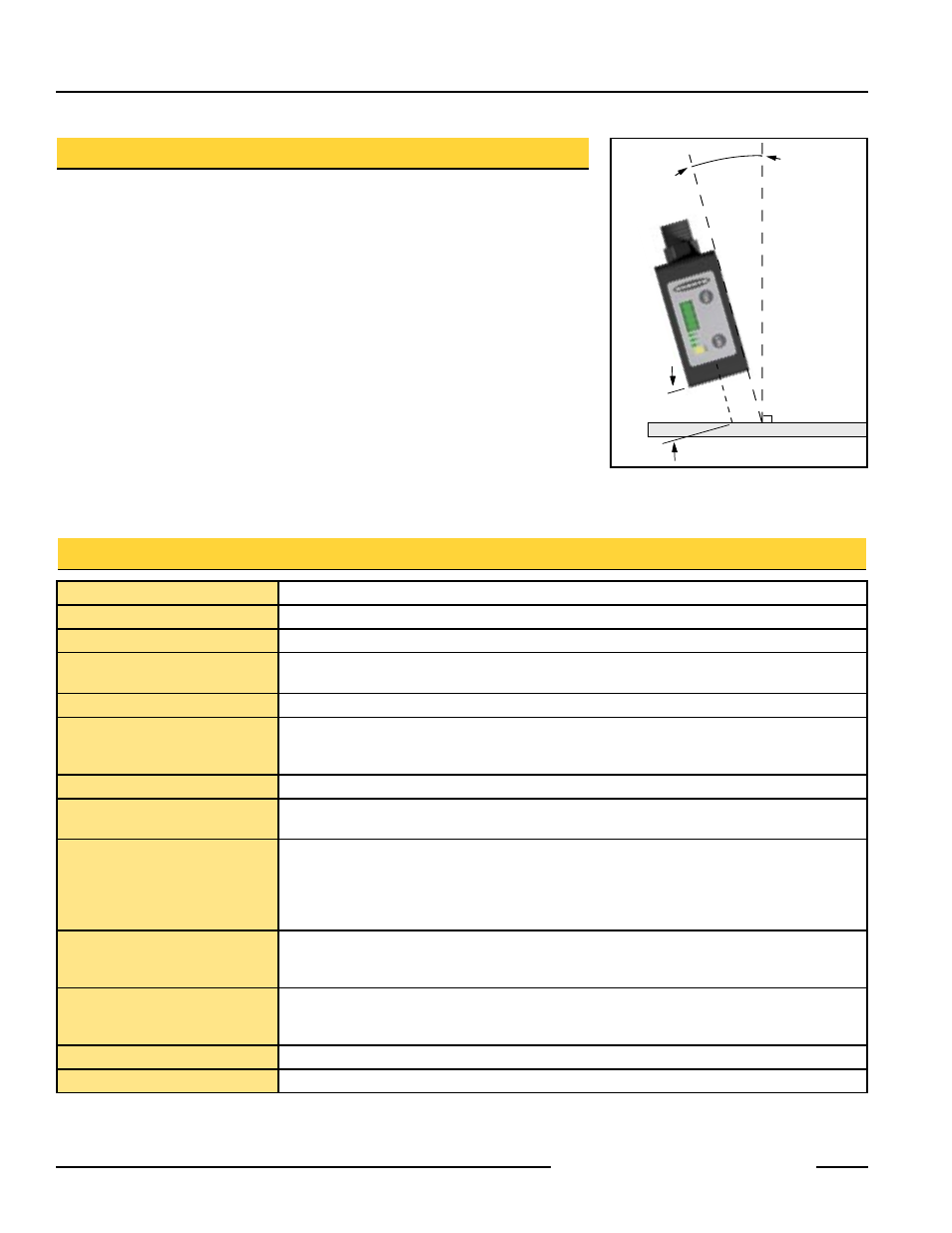
Figure 5. Mount sensor 15° from
perpendicular when sensing a
glossy surface
Installing the Color Sensor
NOTE: When sensing glossy surfaces, install the sensor at approximately a 15° angle
with respect to the target. See Figure 5.
1. Determine the best position for the swivel connector (back, side, or bottom of the
sensor).
2. Measure the appropriate operating distance from the front surface of the sensor
optics to the point where the sensor is to be fastened. Typically, the ideal distance
is 20 mm (0.8").
3. Fasten the sensor to its intended location using two screws (M4x35 or longer). Any
two of three holes in the housing may be used for this purpose.
4. Attach the power cable to the sensor’s connector; see hookups on page 7.
NOTE: When the sensor is ON, the white emitter beam is ON and a message
(“run” or “rund”) appears on the 4-digit status display.
Sensing Beam
Pulsed white LED (400 to 700 nm)
Sensing Receiver
Solid-state photodiode device with R, G, B filters
Sensing Range
20 mm (0.8") typical; varies depending on sensor configuration
Supply Voltage
10 to 30V dc, 2 V pp max ripple
40 mA max @ 24V dc (excluding output current)
Supply Protection Circuitry
Protected against reverse polarity, over-voltage, and transient voltage
Output Configuration
3 PNP or 3 NPN outputs, depending on model
30V dc max
Saturation Voltage: < 2V
Output Rating
100 mA maximum load per output channel
Output Protection
Protected against output short-circuit, continuous overload, transient over-voltages, and false pulse on
power up
Output Response Time
QC50 models: 335 microseconds
QCX50 models: Selectable 5 ms (normal) or 1 ms
NOTE: 500 ms delay at power-up; outputs do not conduct during this time.
QC50 models
QCX50 models
Gate ON-time: 335 microseconds
700 microseconds
Gate OFF-time: 170 microseconds
400 microseconds
Adjustments
2 push buttons (Set and Select)
• Color scanning, color mode, delay and tolerance
• Manual adjustment of color channels, sensing mode and tolerance level
Indicators
4-Digit LCD Display: indicates sensing mode, display information, tolerance level, channel status
Yellow Output LED: ON when any output is conducting
3 Green Channel Output Status LEDs: ON when its corresponding channel output is conducting
Construction
ABS shock-resistant housing; glass window and lens
Environmental Rating
IEC IP62