Qc50 series true color sensor, Indicator displays – Banner QC50 Series User Manual
Page 4
QC50 Series True Color Sensor
4
31UHY&
Banner Engineering Corp.
•
Minneapolis, MN U.S.A.
www.bannerengineering.com • Tel: 763.544.3164
QC50 Series True Color Sensor
P/N 111523 rev. B
5
Banner Engineering Corp.
•
Minneapolis, MN U.S.A.
www.bannerengineering.com • Tel: 763.544.3164
������������
������������
�������������������
�����������
������������������
}
����������������������
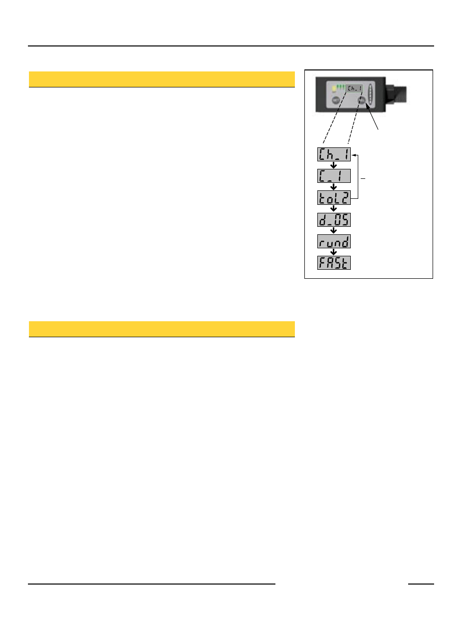
Figure 4. Sequential display of setting
Indicator Displays
To review the sensor’s settings, press Select for 2 seconds or more. The output
channel, sensing mode, and tolerance level will then be displayed sequentially (see
Figure 4), followed by the delay interval (applicable to all channels) and normal or fast
mode (for QCX50 models). At the end of the sequence, the display will indicate “run”
or “rund” (depending on the delay setting).
Non-Initialization Display Messages
When using a sensor for the first time, the message “E2Pr” may be displayed (see
Figure 5). This indicates the memory has yet to be used. To correct this situation, set
up a channel according to the procedure described earlier in “Programming Mode.”
When any channel is set up successfully, a “run” or “rund” message is displayed.
Run Mode
Normal sensor operation is called Run mode. The LED indicators and the 4-digit
display indicate current operating status. For example, if the color sensor is detecting
the color for which output 1 is programmed and no delay is selected, the indicators
will appear:
Output (“Out”) LED: ON Yellow
Output 1 Status LED: ON Green
4-digit display: run
Fast Mode
When a QCX50 model sensor is operating in Fast mode, the display will flash “FASt”
for approximately 5 seconds of every 40 seconds.
Application Notes
Using the Gating Function
The output function of the sensor’s color detection can be gated using the sensor’s
red wire (see hookups, page 7). Using this function controls the sensor’s output and
permits output to occur only when “signaled” by the use of the red wire. This output
control feature is most useful when multiple repeats of a color could occur, such as
with registration marks in a margin, yet only one point on the work is needed for an
accurate determination. Gating is also known as triggering, windowing, inhibiting, or
synchronization.
In the sensor’s normal operating state (output enabled, red wire open or low), the
sensor responds to all taught colors (the Output LED, Channel Status LEDs, and
all outputs respond to target conditions). When the red wire is held high (output
disabled, red wire at high supply potential), the sensor does not respond to the taught
colors (LEDs do not light and outputs do not conduct; i.e., inhibit).
Push Button Disable
It is possible to lock out the push buttons to prevent accidental or unauthorized
adjustments on the production floor. See page 5 for the procedure.