World-beam, Qs30af adjustable-field sensor, Specifications – Banner WORLD-BEAM QS30 Series User Manual
Page 8
WORLD-BEAM
®
QS30AF Adjustable-Field Sensor
8
P/N 111384 rev. D
Banner Engineering Corp.
•
Minneapolis, MN U.S.A.
www.bannerengineering.com • Tel: 763.544.3164
Sensing Beam
660 nm visible red
Supply Voltage
10 to 30V dc (10% max. ripple) @ 45 mA max current, exclusive of load
Supply Protection Circuitry
Protected against reverse polarity, over voltage, and transient voltages
Delay at Power-Up
250 ms; outputs do not conduct during this time
Output Configuration
Bipolar: 1 current sourcing (PNP) and 1 current sinking (NPN)
Output Ratings
150 mA maximum load (derate ~ 1 mA/°C above 25°C)
OFF-state leakage current: < 50 µA at 30V dc
ON-state saturation voltage:
NPN: < 200 mV @ 10 mA; < 1V @ 150 mA
PNP: < 1.25V @ 10 mA; < 2V @ 150 mA
Output Protection
Protected against output short-circuit, continuous overload, transient over-voltages, and false pulse on
power up
Output Response Time
1 millisecond
Repeatability
170 microseconds
Adjustments
2 push buttons and remote wire
• Easy push-button configuration
• Manually adjust (+/–) cutoff (push buttons only)
• N.O./N.C. and OFF-delay configuration options (push buttons only)
• Push-button lockout (from remote wire only)
Indicators
8-segment red bargraph: Distance relative to cutoff point
Green LED: Power ON
Yellow LED: Output conducting
Construction
ABS plastic housing; acrylic lens cover
Environmental Rating
IP67, NEMA 6
Connections
5-conductor 2 m (6.5') PVC cable, 9 m (30') PVC cable, or 5-pin integral Euro-style quick-disconnect fitting
Operating Conditions
-10° to +55°C (+14° to 122°F), 90% relative humidity @ 55°C (non-condensing)
Vibration and Mechanical
Shock
All models meet Mil. Std. 202F requirements. Method 201A (Vibration: 10 to 60 Hz max. double amplitude
0.06", maximum acceleration 10G). Also meets IEC 947-5-2 requirements: 30G, 11 ms duration, half sine
wave.
Certifications
Specifications
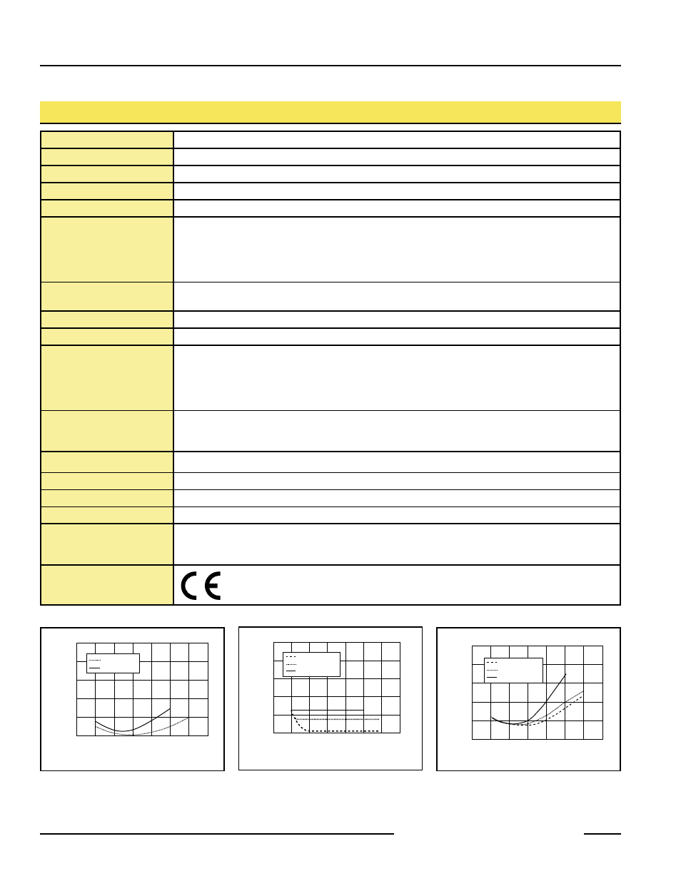
+/- 10
+/- 20
+/- 30
+/- 40
+/- 50
0
0
50
100
150
200
250
300
350
18% Gray Card
6% Black Card
Cutoff Setting (90% White Card)
Cutoff Deviation (mm)
50
40
30
20
10
0
0
50
100
150
200
250
300
350
Cutoff Setting (mm)
Minimum Range
90% White Card
18% Gray Card
6% Black Card
20.0
16.0
12.0
8.0
4.0
0
0
50
100
150
200
250
300
350
90% White Card
18% Gray Card
6% Black Card
Cutoff Setting (mm) with 90% White Card
Hysteresis (% of Cutoff)
Figure 10. QS30AF cutoff point deviation
Figure 11. QS30AF minimum range vs.
cutoff setting
Figure 12. QS30AF hysteresis