L-gage, Lt3 long-range time-of-flight sensor, Two discrete outputs – Banner L-GAGE LT3 Series User Manual
Page 5
L-GAGE
®
LT3 Long-Range Time-of-Flight Sensor –
Two Discrete Outputs
P/N 68503 rev. C
5
Banner Engineering Corp.
•
Minneapolis, MN U.S.A.
www.bannerengineering.com • Tel: 763.544.3164
Push Button
0.04 ≤ “click” ≤ 0.8 sec.
Remote Wire
0.04 sec. ≤ T ≤ 0.8 sec.
Procedure
Result
Procedure
Result
Programming
Mode
• Push and hold either
push button for
> 2 seconds*
• Corresponding TEACH
LED turns ON
No action required
• Briefly “click” the
other button
• Corresponding TEACH
LED turns ON
• Sensor is waiting for first
limit
Teach
First
Limit
• Position the target for
the first limit**
• “Click” either push
button
• Both TEACH LEDs flash at
2 Hz, alternating Red and
Green
• Sensor learns first limit
and waits for second limit
• Position the target for the first
limit**
• Triple-pulse the remote line
• Both TEACH LEDs turn ON
• Sensor learns first limit and
waits for second limit
• Both TEACH LEDs flash at
2 Hz, alternating Red and
Green
Teach
Second
Limit
• Position the target for
the second limit
• “Click” either push
button
• Both TEACH LEDs go OFF
• Sensor learns second
limit and returns
automatically to RUN
mode
• Position the target for the second
limit
• Single-pulse the remote line
• Both TEACH LEDs go OFF
• Sensor learns second limit
and returns automatically to
RUN mode
Teaching Identical Limits for Both Outputs Simultaneously
* Sensor will return to RUN mode if first TEACH condition is not registered within 120 seconds.
** Press and hold the same push button (or hold the remote line high) > 2 seconds (before teaching the second limit) to exit PROGRAM mode
without saving any changes. The sensor will revert to the last saved program.
D
or
or
D
D
D
D
D
D
or
or
D
D
D
D
D
D
or
or
D
D
D
D
D
D
or
or
D
D
D
D
D
T
T
T T T
T T T T T T T
T
T
T
T T
T
T
T T T
T T T T T T T
T
T
T
T T
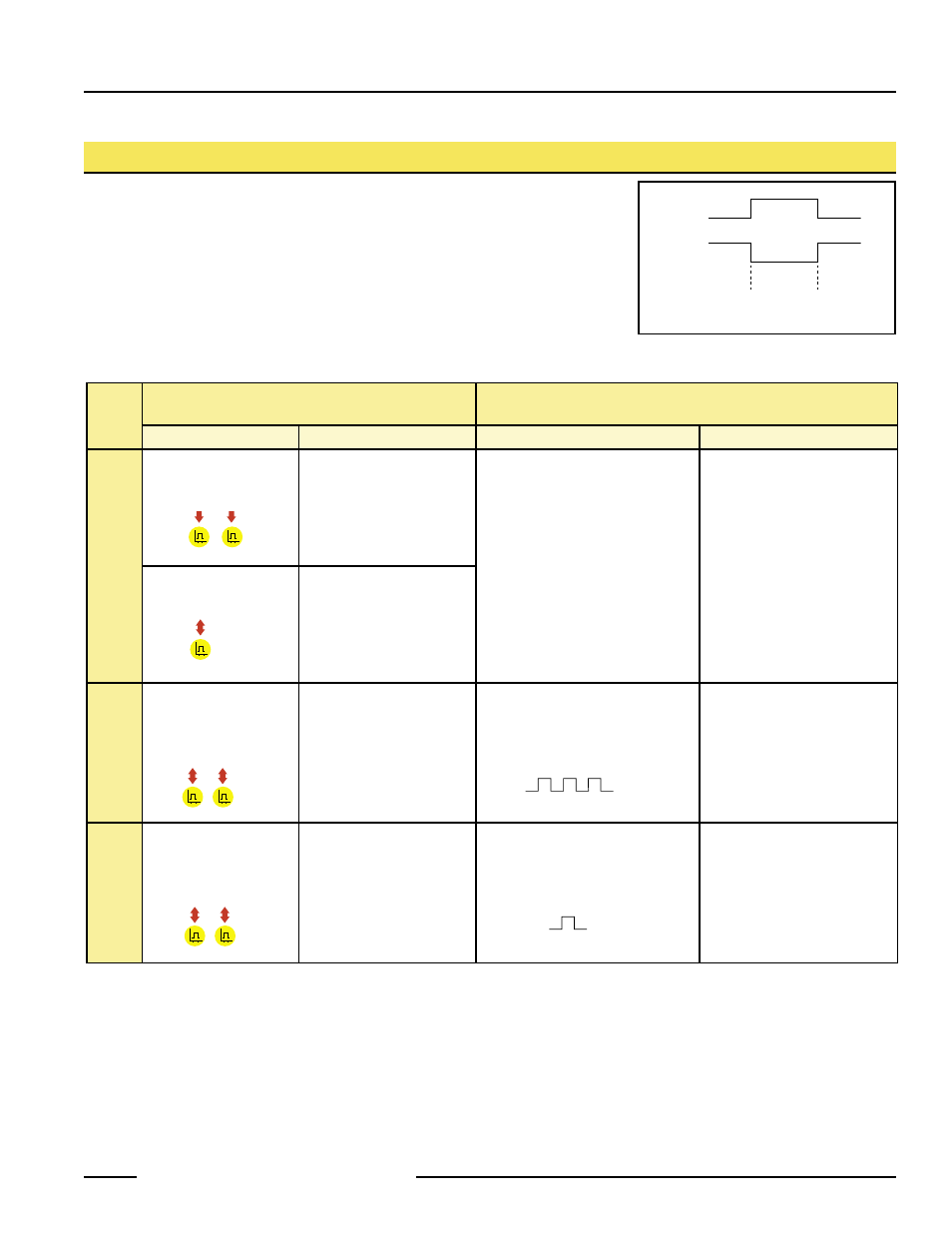
To set both outputs at exactly the same limits, they may be set simultaneously. This
will result in complementary outputs (while one output is conducting, the other is not).
Hysteresis will be controlled by Output 1 and Output 2 will follow.
Output 1
Near
Limit
Far
Limit
Output 2
Figure 6. Both outputs have identical limits,
but are complementary