L-gage, Lt3 long-range time-of-flight sensor, Two discrete outputs – Banner L-GAGE LT3 Series User Manual
Page 2: Theory of operation, Programming, Response speed, Sensor setup, Window limits
L-GAGE
®
LT3 Long-Range Time-of-Flight Sensor –
Two Discrete Outputs
2
P/N 68503 rev. C
Banner Engineering Corp.
•
Minneapolis, MN U.S.A.
www.bannerengineering.com • Tel: 763.544.3164
Theory of Operation
A short electrical pulse drives a semiconductor laser diode to emit a pulse of light. The
emitted light is collimated through a lens, which produces a very narrow laser beam.
The laser beam bounces off the target, scattering some of its light through the sensor’s
receiving lens to a photodiode, which creates an electrical pulse. The time interval
between the two electrical pulses (transmitting and receiving the beam) is used to
calculate the distance to the target, using the speed of light as a constant.
Multiple pulses are evaluated by the sensor’s microprocessor, which calculates the
appropriate position value. The discrete (switched) output energizes whenever the
target is located between the user-programmed discrete window limits. Window
limits for both discrete outputs may be the same, or they may be programmed
independently.
Programming
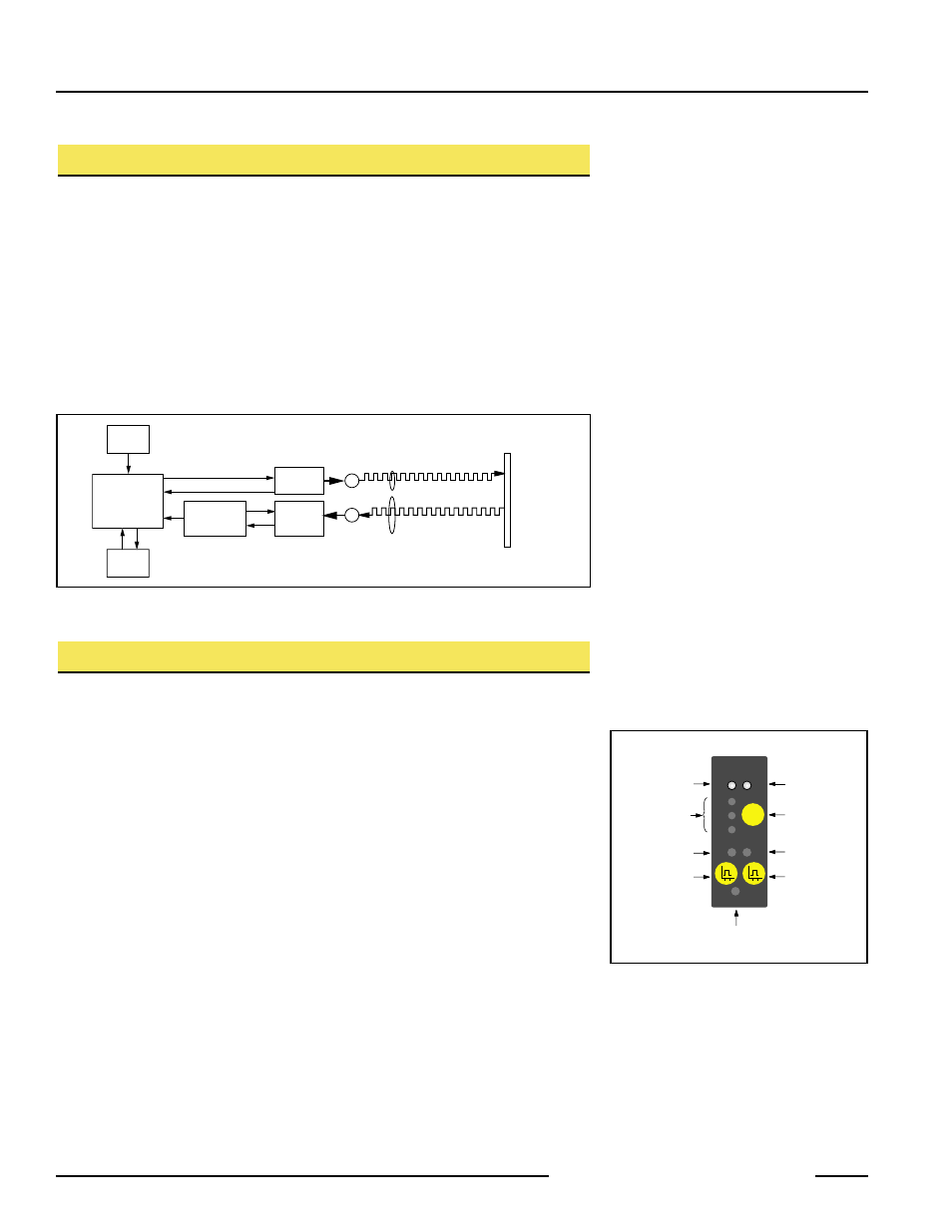
Response Speed
Prior to setting window limits, use the sensor’s Speed push button to toggle between
the three response speed settings. The selected speed will be indicated by one of the
three Response Speed indicator LEDs (see Figure 2). See Specifications for further
information.
Sensor Setup
Allow 30 minutes after power-up to allow the sensor’s internal temperature to stabilize,
before operating or attempting to program the sensor. If the sensor will be used in
applications where the temperature is several degrees higher or lower than ambient,
allow the sensor to stabilize in that condition before programming the window limits.
(Range will decrease as the sensor warms up.)
The laser enable feature allows the sensor to be continually powered, and enabled only
when being used. This eliminates the need for the extended warm-up period between
uses.
The sensor’s red Signal LED indicates the condition of the received signal from the
object being measured. When programming window limits, this LED must be ON solid
(not flashing) for the sensor to accept the setting. On diffuse-mode models, to ensure
that the received signal will not be marginal during operation, move the target object
300 mm beyond the furthest desired set point during setup, and verify that the signal
LED is still ON solid.
Window Limits
Window limits may be taught to the sensor in several ways. The following methods
(beginning on page 4) describe the programming procedures using the push buttons on
the top of the sensor or via remote programming (remote TEACH).
Microprocessor
User
Interface
Emitter
Circuitry
Analog
Signal
Processing
Time-of-Flight
Engine
Output
Circuitry
Laser
Emitter
Lenses
Target
Receiver
Element
E
R
Figure 1. Theory of operation
SIGNAL
OUTPUT
FAST
MED
SLOW
TEACH
POWER
SPEED
Signal LED
Output LED
Response Speed
Indicators
Discrete Output 1
Teach LED
Discrete Output 2
Teach LED
Discrete Output 1
Programming
Push Button
Discrete Output 2
Programming
Push Button
Power ON/OFF LED
Response Speed
Push Button
D
D
Figure 2. Sensor features