L-gage, Lt3 long-range time-of-flight sensor, Two discrete outputs – Banner L-GAGE LT3 Series User Manual
Page 3
L-GAGE
®
LT3 Long-Range Time-of-Flight Sensor –
Two Discrete Outputs
P/N 68503 rev. C
3
Banner Engineering Corp.
•
Minneapolis, MN U.S.A.
www.bannerengineering.com • Tel: 763.544.3164
Push-Button Programming
Both outputs may be taught simultaneously, when complementary operation is required
(while one output is conducting, the other is not). When taught separately, each output
may be taught different limits (one output may be taught a window, and the other may
be programmed for background suppression, for example).
Remote Programming
To program the sensor remotely or to disable the keypad, the Remote Programming
function may be used. Disabling the keypad prevents accidental or unauthorized
adjustment of any programming settings. Connect the yellow wire of the sensor to +5
to 24V dc, with a remote programming switch connected between them.
NOTE: The impedance of the remote teach input is 55 kΩ.
Programming is accomplished by following a sequence of input pulses (see pages 4
and 5). The duration of each pulse (corresponding to a push button “click”), and the
period between multiple pulses, are defined as “T”: 0.04 seconds < T < 0.8 seconds.
Teaching Discrete Limits for Background Suppresson
For some applications, ignoring objects beyond a certain distance may be required. To
suppress the background, place a target object at the selected distance, and teach the
position twice. The sensor’s discrete output will activate when an object is detected
between the sensor’s minimum sensing distance and the taught position.
NOTE: The sensor allows for some forgiveness in this procedure. If the two limits are
not exactly the same (but less than 20 mm apart), the sensor will put the set
point at the “average” of the two limits.
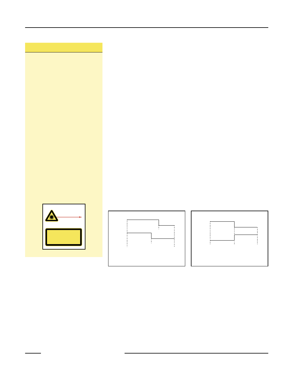
Output 1 and Output 2 may be taught independent limits for background suppression
(see Figure 3).
To set both outputs at exactly the same limits, set them simultaneously. This will result
in complementary outputs (while one output is conducting, the other is not; see
Figure 4). Hysteresis will be controlled by Output 1 and Output 2 will follow.
Class 2 Safety Notes
Low-power lasers are by definition
incapable of causing eye injury within
the duration of the blink, or aversion
response, of 0.25 seconds. They must
also emit only visible wavelengths (400-
700 nm). Therefore, an eye hazard can
exist only if an individual overcomes
the natural aversion to bright light and
stares directly into the laser beam.
These lasers are required to have a
“hazard” label and to have an indicator
light to indicate that laser emission is
occurring.
When operating a class 2 laser:
• Do not permit a person to stare
directly into the beam
• Do not point the laser at a person’s
eye at close range
Beam Paths:
The beam emitted by a class 2 laser
product should be terminated at the
end of its useful path. Open laser beam
paths should be located above or below
eye level, where practical.
RADIANT POWER 0.5 mW
650 - 670 nm
COMPLIES WITH 21 CFR PART
1040.10 AND EN60825-1:1994
DO NOT STARE INTO BEAM
CLASS 2 LASER PRODUCT
LASER LIGHT
Avoid exposure -
laser light emitted
from this aperture
Output 1
Near
Sensing
Range
Teach
Point 2
Output 2
Far
Sensing
Range
Teach
Point 1
Output 1
Near
Sensing
Range
Output 2
Far
Sensing
Range
Teach
Point
Figure 3. Each output has its own limit for
background suppression
Figure 4. The two outputs share identical
limits for background suppression,
but are complementary