Specifications, 2 and in, Background reflectivity and placement – Banner Q40 Series User Manual
Page 3: Figure 3. reflective background - problem, Figure 4. reflective background - solution, Figure 5. object beyond cutoff - problem, 3, these elements align vertically; in, Figure 6. object, Beyond cutoff - solution
on page 2). The sensing axis becomes important in situations like those illustrated in
Figure 5. Object beyond cutoff - problem
on page 3 and
Object beyond cutoff - solution
on page 3.
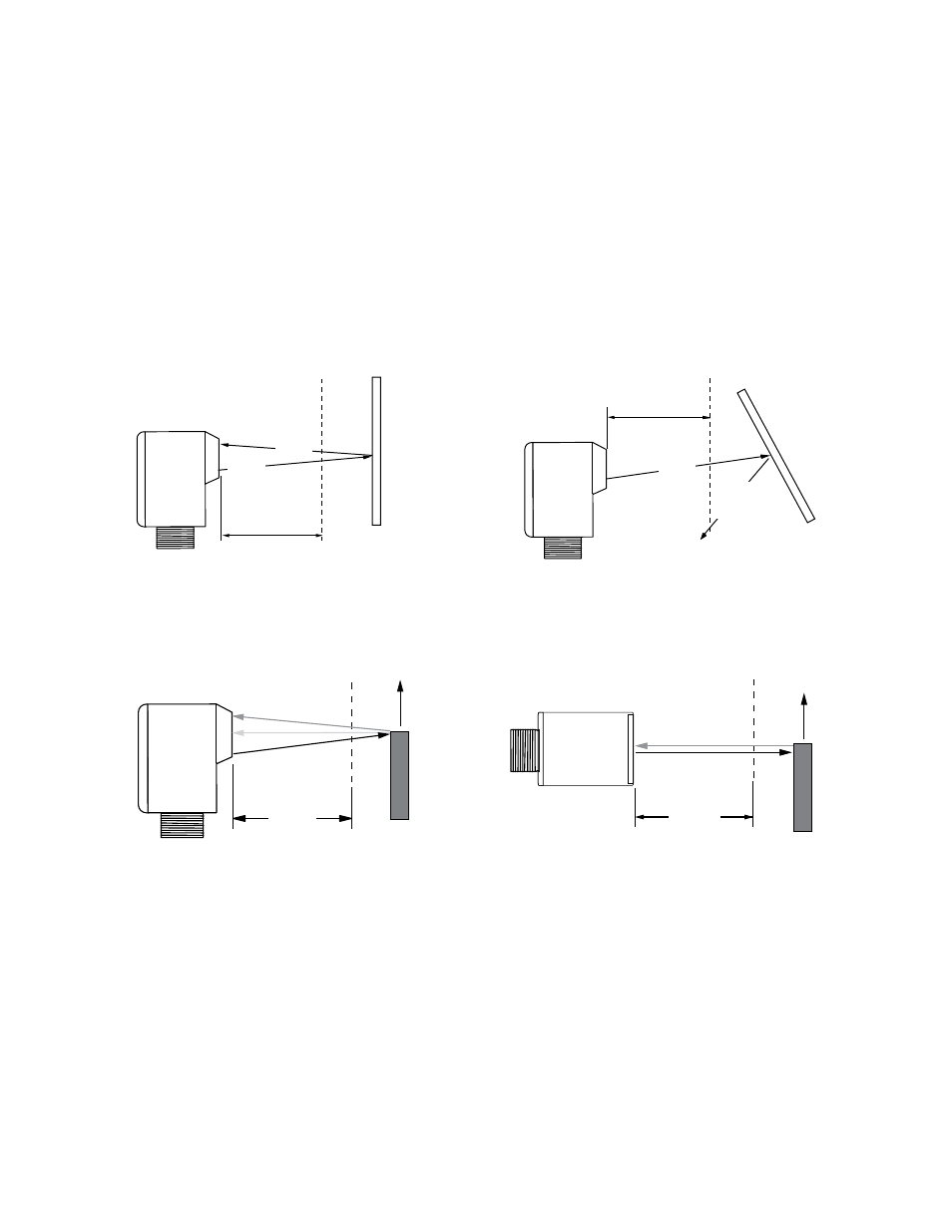
Background Reflectivity and Placement
Avoid mirror-like backgrounds that produce specular reflections. False sensor response will occur if a background surface reflects the sensor’s light more strongly to the
near detector (R1) than to the far detector (R2). The result is a false ON condition (
Figure 3. Reflective background - problem
on page 3). Use of a diffusely-reflective
(matte) background will cure this problem. Other possible solutions are to angle the sensor or angle the background (in any plane) so the background does not reflect back
to the sensor (see
Figure 4. Reflective background - solution
on page 3). Position the background as far beyond the cutoff distance as possible.
An object beyond the cutoff distance, either moving or stationary (and when positioned as shown in
Figure 5. Object beyond cutoff - problem
on page 3), can cause
unwanted triggering of the sensor because it reflects more light to the near detector than to the far detector. The problem is easily remedied by rotating the sensor 90°
(
Figure 6. Object beyond cutoff - solution
on page 3) to align the sensing axis horizontally. The object then reflects the R1 and R2 fields equally, resulting in no false
triggering. A better solution, if possible, may be to reposition the object or the sensor.
Unwanted triggering of the sensor from an object beyond the cutoff can also be caused by attempting to sense a small object that is moving perpendicular to the sensor
face, or by an object moving through the off-center position shown in
Figure 5. Object beyond cutoff - problem
on page 3. Making the object larger, centering the sensor
relative to the object, or rotating the sensor to place the sensing axis perpendicular to the longer dimension of the object (
Figure 6. Object beyond cutoff - solution
on page
3) will solve the problem.
E
R2
R1
Q40 sensor
E = Emitter
R1 = Near Detector
R2 = Far Detector
Fixed Sensing Field
Strong
Direct
Reflection
to R1
Core of
Emitted
Beam
Cutoff
Distance
Reflective
Background
Figure 3. Reflective background - problem
E
R2
R1
Q40 sensor
E = Emitter
R1 = Near Detector
R2 = Far Detector
Cutoff
Fixed Sensing Field
Strong Direct
Reflection
Away
From Sensor
Core of
Emitted
Beam
Cutoff
Distance
Reflective
Background
Figure 4. Reflective background - solution
R1 = Near Detector
R2 = Far Detector
E = Emitter
Reflective
Background
or
Moving Object
E
R2
R1
Q40 sensor
Fixed
Sensing
Field
Cutoff
Distance
Figure 5. Object beyond cutoff - problem
E = Emitter
R2 = Far Detector
R1 = Near Detector
E, R2, R1
Q40 sensor
Fixed
Sensing
Field
Cutoff
Distance
Reflective
Background
or
Moving Object
Figure 6. Object beyond cutoff - solution
Specifications
Supply Voltage and Current
10 to 30V dc (10% max. ripple)
Supply current (exclusive of load current):
Emitters: 25 mA
Receivers: 20 mA
Polarized Retroreflective: 30 mA
Fixed-Field: 35 mA
Supply Protection Circuitry
Protected against reverse polarity and transient voltages
Repeatability
Opposed mode: 375 μs
Retro and Fixed-Field: 750 μs
Repeatability and response are independent of signal strength
Indicators
Two LEDs (Green and Yellow)
Green ON steady: power to sensor is ON
Green flashing: output is overloaded
Yellow ON steady: N.O. output is conducting
Yellow flashing: excess gain marginal (1 to 1.5x) in light condition
Q40 Sensors - dc-Voltage Series Installation Guide
P/N 116167 Rev. A
www.bannerengineering.com - tel: 763-544-3164
3