Banner Q40 Series User Manual
Q40 sensors - dc-voltage series installation guide, Self-contained, dc-operated sensors, Models
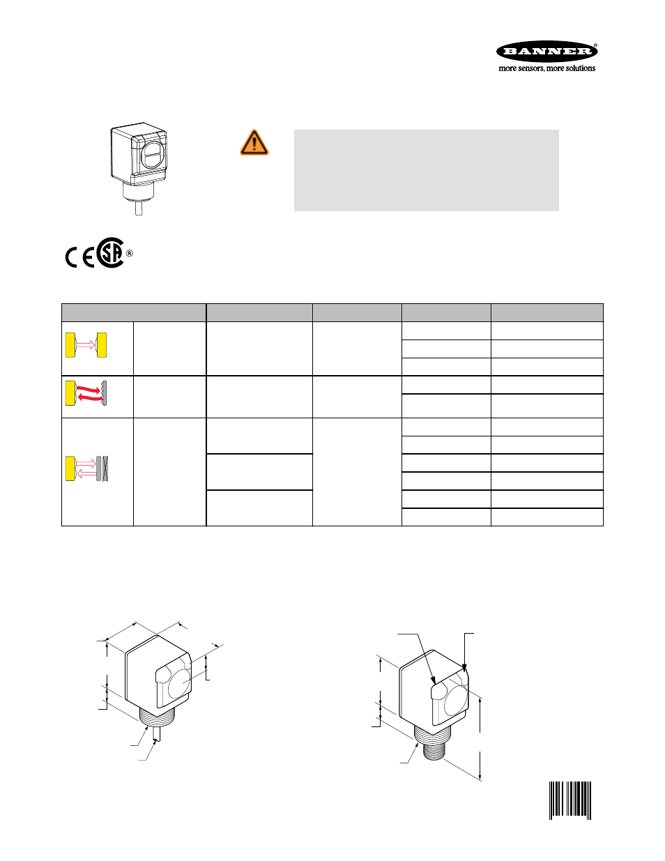
Self-contained, dc-operated sensors
WARNING: Not To Be Used for Personnel Protection
Never use this product as a sensing device for personnel protection. Do-
ing so could lead to serious injury or death. This product does NOT include
the self-checking redundant circuitry necessary to allow its use in personnel
safety applications. A sensor failure or malfunction can cause either an ener-
gized or de-energized sensor output condition.
Models
Sensing Mode
Range
LED
Output
Model*
OPPOSED
Opposed
60 m (200')
Infrared 950 nm
-
Q406E
NPN
Q40SN6R
PNP
Q40SP6R
P
POLAR RETRO
Polarized Retro-re-
flective
6 m (20')
Visible Red 680 nm
NPN
Q40SN6LP
PNP
Q40SP6LP
FIXED-FIELD
Fixed Field
200 mm (8") cutoff
Infrared 880 nm
NPN
Q40SN6FF200
PNP
Q40SP6FF200
400 mm (16") cutoff
NPN
Q40SN6FF400
PNP
Q40SP6FF400
600 mm (24") cutoff
NPN
Q40SN6FF600
PNP
Q40SP6FF600
* Standard 2 m (6.5') cable models are listed.
• 9 m (30') cable: add suffix "W/30" (e.g., Q406E W/30).
• 4-pin Euro-style QD models: add suffix "Q" (e.g., Q406EQ). A model with a QD connector requires a mating cable.
Dimensions
Cabled Models
QD Models
40.1 mm
(1.58")
50.0 mm
(1.97")
46.0 mm
(1.81")
20.1 mm
(0.79")
(Jam Nut Supplied)
Lens Centerline
19.8 mm
(0.78")
M30 x 1.5 Thread
2 m (6.5') Cable
50.0 mm
(1.97")
(Jam Nut Supplied)
19.8 mm
(0.78")
M30 x 1.5 Thread
82.5 mm
(3.25")
Green LED
Power Indicator
Yellow LED
Output Indicator
Q40 Sensors - dc-Voltage Series Installation Guide
P/N 116167 Rev. A
5/30/2012
0 116167
0