Hookups, Fixed-field mode overview, Excess gain – Banner Q40 Series User Manual
Page 2: Set-up tips
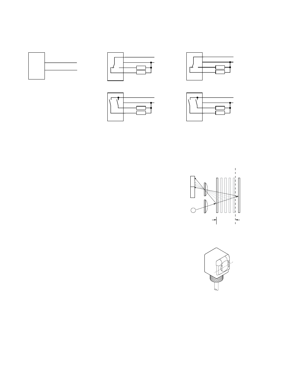
Hookups
NPN (Sinking) Outputs
PNP (Sourcing) Outputs
Cabled Emitters
Standard Hookup
Standard Hookup
bn
bu
10-30V dc
+
–
bn
bu
wh
bk
+
10 - 30V dc
–
Load
Load
bu
bn
wh
bk
+
10 - 30V dc
–
Load
Load
Alarm Hookup
Alarm Hookup
NOTE: QD hookups are functionally identical.
bn
bu
wh
bk
10 - 30V dc
Load
Alarm
+
–
bn
bu
wh
bk
10 - 30V dc
Load
Alarm
+
–
Fixed-Field Mode Overview
Q40 Series self-contained fixed-field sensors are small, powerful, infrared diffuse mode sensors with far-limit cutoff. The high excess gain of these sensors makes it possi-
ble for them to detect objects of low reflectivity. The fixed-field design makes them ideal for detecting a part or surface that is directly in front of another surface, while
ignoring the surface in the background.
Excess Gain
The excess gain curves for these products are available in the Photoelectric Sensors catalog or on the Ban-
ner website. They show excess gain vs. sensing distance for sensors with 200 mm, 400 mm, and 600 mm
(8", 16", and 24") cutoffs. Maximum excess gain for all models occurs at a lens-to-object distance of about
40 mm (1.57"). Sensing at or near this distance will make maximum use of each sensor’s available sensing
power.
Backgrounds and background objects must always be placed beyond the cutoff distance.
These excess gain curves were generated using a white test card of 90% reflectance. Objects with reflectiv-
ity of less than 90% reflect less light back to the sensor, and thus require proportionately more excess gain
in order to be sensed with the same reliability as more reflective objects. When sensing an object of very
low reflectivity, it may be especially important to sense it at or near the distance of maximum excess gain.
The effects of object reflectivity on cutoff distance, though small, may be important for some applications.
Sensing of objects of less than 90% reflectivity causes the cutoff distances to be “pulled” slightly closer to
the sensor. For example, an excess gain of 1 for an object that reflects 1/10 as much light as the 90% white
card is represented by the heavy horizontal graph line at excess gain = 10. An object of this reflectivity
results in far limit cutoffs of approximately 190 mm, 250 mm, and 390 mm (7.48", 9.84", and 15.4") for the
200 mm, 400 mm, and 600 mm (8", 16", and 24") cutoff models, respectively.
For highest sensitivity, the sensor-to-object distance should be such that the object will be sensed at or near
the point of maximum excess gain. The background must be placed beyond the cutoff distance. Following
these two guidelines makes it possible to detect objects of low reflectivity, even against close-in reflective
backgrounds.
R1
R2
Lenses
Object
A
Object B
or
Background
Sensing
Range
Cutoff
Distance
E
Receiver
Elements
Near
Detector
Far
Detector
Emitter
Object is sensed if amount of light at R1
is greater than the amount of light at R2
Figure 1. Fixed-field Concept
Sensing
Axis
R2
R1
E
As a general rule, the most reliable sensing of an object
approaching from the side occurs when the line of ap-
proach is parallel to the sensing axis.
Figure 2. Fixed-field sensing axis
Set-Up Tips
In the drawings and discussion in
on page 2 and in
Background Reflectivity and Placement
on page 3, the letters E, R1, and R2 identify how the sensor’s
Figure 3. Reflective background - problem
3,
Figure 4. Reflective background - solution
Figure 5. Object beyond cutoff - problem
on page 3, these elements align vertically; in
on page 3, they align horizontally. Note how the pattern on the sensor’s lens helps to define the sensing axis of the sensor (
Q40 Sensors - dc-Voltage Series Installation Guide
2
www.bannerengineering.com - tel: 763-544-3164
P/N 116167 Rev. A