Wiring, Push button lockout – Banner U-GAGE QT50U Ultrasonic Sensors User Manual
Page 9
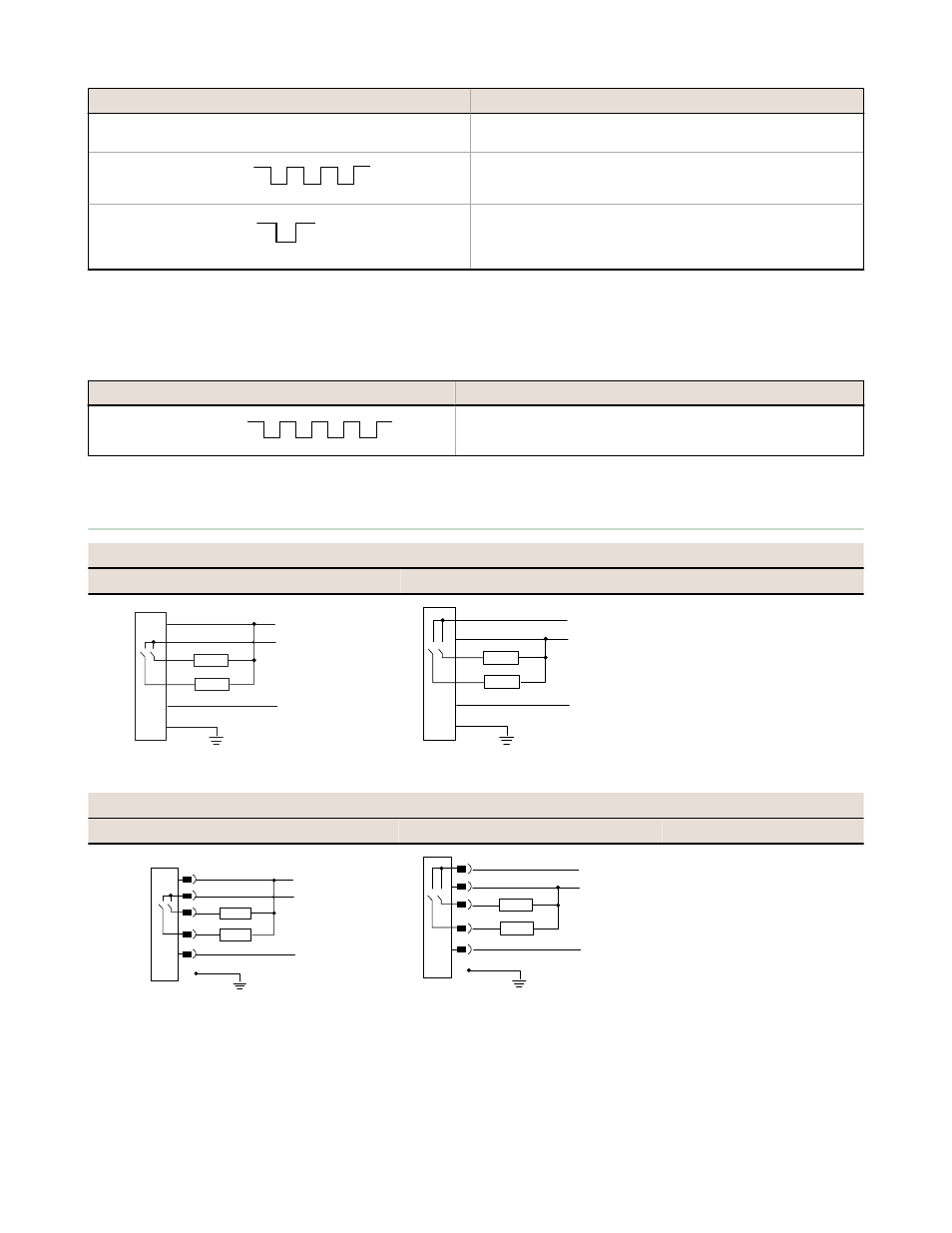
Action
Result
Position the target at the sensing window midpoint/suppression
limit
Triple-pulse the remote line
T
T
T
T
T
Both output LEDs flash red
Single-pulse the remote line
T
Both output LEDs turn solid amber and the sensor stores the
sensing window on Output 1 and the suppression limit on Output 2.
The sensor returns to RUN mode.
Push Button Lockout
The Push Button Lockout feature enables or disables the keypad to prevent unauthorized personnel from adjusting the
programming settings. This feature is not available using the buttons.
Procedure (0.04 s < T < 0.8 s)
Result
Four-pulse the remote line
T
T
T
T
T
T
T
Push buttons are either enabled or disabled, depending on previous
condition.
Wiring
Cabled Models
NPN Wiring
PNP Wiring
4
5
1
3
2
10–30 V dc
shield
Remote Teach
0–2 V dc
Load 1
Load 2
See note below
+
−
4
5
1
3
2
10–30 V dc
shield
Remote Teach
0–2 V dc
Load 1
Load 2
See note below
+
−
1 = brown
2 = white
3 = blue
4 = black
5 = gray
QD Models
NPN Wiring
PNP Wiring
4
5
1
3
2
10–30 V dc
shield
Remote Teach
0–2 V dc
Load 1
Load 2
See note below
+
−
4
5
1
3
2
10–30 V dc
shield
Remote Teach
0–2 V dc
Load 1
Load 2
See note below
+
−
1 = brown
2 = white
3 = blue
4 = black
5 = yellow or gray
NPN or PNP hookup must agree with DIP-switch settings. Banner Engineering Corp. recommends connecting the shield
wire to earth ground or DC common.
U-GAGE QT50UDB Series Sensors with Dual-Discrete Outputs
P/N 110112 Rev. B
www.bannerengineering.com - tel: 763-544-3164
9