Bird Technologies 3140 Display User Manual
Page 25
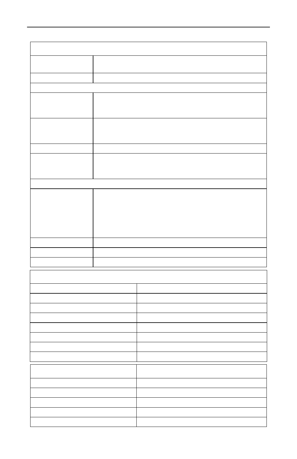
Performance Specifications
15
Interface Specs
Main line
Diameters and center conductor setbacks per Bird
drawings.
Connectors
One DB9(M), three N(F)
DB9 connector pinout
Pin 1 = “FWD”
Analog output for forward RF power. 0 – 5.0 Vdc
proportional to RF power, 1 kohm
impedance. Fullscale RF input = 4.0V output.
Pin 3 = “RFL”
Analog output for reflected RF power. 0 – 5.0 Vdc
proportional to RF power, 1 kohm
impedance. Fullscale RF input = 4.0V output.
Pin 5 = “Power”
Power supply input. +11 to +18 Vdc, < 0.1 A.
Pin 9 = “Zeroline” Short this pin to ground to zero out any input offsets.
Normally floating. Unit can be zeroed whenever the unit is
powered up and there is no RF power being applied.
Pins 2,4,6–8 = GND
N(F) Testports
Ports are labeled Forward, Test, and Reflected. Forward
and reflected testports include attached loads. These
testports must be terminated with the load, or some other
good termination such as a power sensor, during normal
operation to prevent measurement errors. Loads can
removed from the unit if desired without affecting calibration.
Forward
Testport output is a sample of the forward RF signal.
Test
Testport output is a nondirectional sample of the RF.
Reflected
Testport output is a sample of the reflected RF signal.
Environmental Specs
Temperature, Operating
0 to +50 °C (32 to 122 °F)
Temperature, Storage
–20 to +80 °C (–4 to +176 °F)
Altitude, Max
3,000 m (10,000 ft) above sea level
Humidity, Max
95% noncondensing
CE
CE compliant
ROHS
ROHS compliant
Dimensions
Refer to “Dimensions” on page 16.
Weight
See table below.
Line Size
Weight, Max
7/8”
3 lbs (1.5 kg)
1-5/8”, unflanged
3.5 lbs (1.6 kg)
1-5/8”, flanged
5.5 lbs (2.5 kg)
3-1/8”, unflanged
4.5 lbs (2.0 kg)
3-1/8”, flanged
8 lbs (3.6 ks)