Bird Technologies 3140 Display User Manual
Page 13
Installing & Operating Instructions - TPM
3
Chapter 2
Installing & Operating Instructions - TPM
Note:
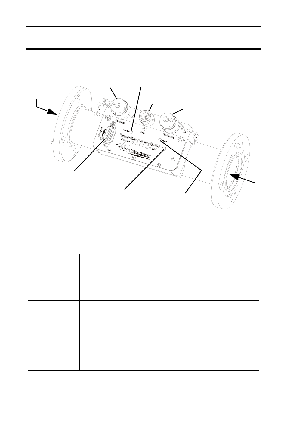
The label on the top of the unit identifies the
connectors and ports. They are defined as follows:
Note:
TPM units are terminated at the time of assembly.
SOURCE
Connect to the source of the RF signal
(transmitter side)
LOAD
Connect to the load of the RF signal
(antenna/dummy load)
FORWARD
The forward directional coupler port. Terminate
this port in 50 ohms at all times.*
REFLECTED
The reflected directional coupler port. Terminate
this port in 50 ohms at all times.*
TEST
A non directional sample port. No termination is
required.
* - If these ports are not terminated in 50 ohms, power
measurements will not be accurate.
To Source
Operation LED
Calibration Cover
FWD Port
RFL
Port
Test
Port
Calibration Cover
Note:
Figure shown with terminations assembled.
To Load
Communication
Connector
Figure 1
TPM
TPM1 Shown