Passive calibration, Figure 6 forward calibration set-up – Bird Technologies 3140 Display User Manual
Page 20
Bird Electronics Corporation
10
Passive Calibration
Calibrate the TPM on the transmitter it is monitoring. Also a refer-
ence power meter is needed to measure the output of the test port on
the TPM (model 7006A250). This calibration can be performed while
transmitting on air (forward only) or into a dummy load. Coupling
calibration data for the TPM is also needed.
By using several different power levels, an equation or lookup table
can be generated for the voltage output of the TPM as a function of
power level at the frequency of calibration.
1. Install the TPM to the transmission line. Refer to “Installing the
2. Remove the load from the Fwd testport.
3. Connect the calibration standard to the Fwd testport.
4. Apply RF power.
5. Record the transmitter frequency displayed and find the listing
closest to it on the TPM’s coupling calibration data card.
Note:
Make note of the calibration factor.
6. Enter the calibration factor into the calibration standard’s offset
function.
7. Measure the power on the calibration standard and voltage on the
TPM output simultaneously.
8. Record the voltage verses power.
9. Turn the unit around and repeat steps 1 to 7 for Reflected calibration.
Note:
Reflected fullscale is 1/10th of forward fullscale.
Note:
Calibrating the reflected port is often optional.
Check with the FCC or other ruling body to determine if it is
necessary or not.
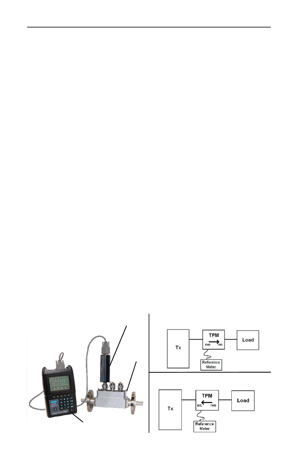
Figure 6
Forward Calibration Set-Up
TPM
Connector
Figure 7
Reflected Calibration Set-Up
Calibration Standard
Figure 5
Calibration Kit