Chapter 5 performance specifications, Transmitter power meter (tpm), Model naming table – Bird Technologies 3140 Display User Manual
Page 23
Performance Specifications
13
Chapter 5
Performance Specifications
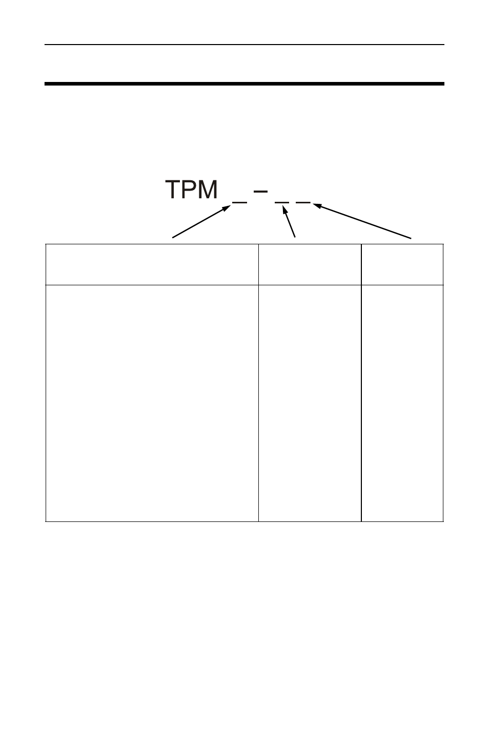
Transmitter Power Meter (TPM)
Model Naming Table
Note:
Models TPM 3 x - LV and models TPM x - US are
not offered for sale.
Frequency Range - Model dependent. See table above
Forward Fullscale Power - Model dependent. See table below.
Note:
Maximum safe line power may be lower than
fullscale power. See Line Section Max RF Power vs Frequency
table on page 20 for recommended max safe line powers at the
active frequency.
Line Size and Interface Style
Frequency
Band*
Power
Range*
7xy = 7/8” with QC connectors, where x is
the input connector and y is the output
connector. Possible values of x and y are:
L = 54 - 88 MHz
F = 88 - 108 MHz
H = 174 - 216 MHz
U = 470 - 806 MHz
V = Very Low
L = Low
M = Medium
H = High
S = Very High
A =N(F)
B = N(M)
C = LC(F)
D = 7/8” Flange
H = 7-16 DIN(F)
J = 7-16 DIN(M)
K = UHF(F)
L = UHF(M)
1 = 1-5/8” Flanged 1U = 5/8”
Unflanged “recessed”
1UF = 1-5/8” Unflanged “flush”
3 = 3-1/8” Flanged 3U = 3-1/8”
Unflanged “recessed”
3UF = 3-1/8” Unflanged “flush”