Installing the tpm – Bird Technologies 3140 Display User Manual
Page 14
Bird Electronics Corporation
4
Installing the TPM
The TPM has two RF connectors (Source and Load) that connect to the
transmission line, three test port connectors that are type N female
connectors (Forward, Reflected, and Test), and one nine-pin subminia-
ture communication connector (DB-9 Male).
1. Do the following:
•
Connect the RF connector labeled Source to the transmitter
side of the transmission line.
•
Connect the RF connector labeled Load to the antenna or load
side of the transmission line.
•
Use an appropriate coupling kit to secure the TPM in place.
2. Connect the DB-9 connector to a single channel on Model 3140A
power meter panel, or to an alternate appropriate power supply
and voltmeters that will indicate the forward and reflected power.
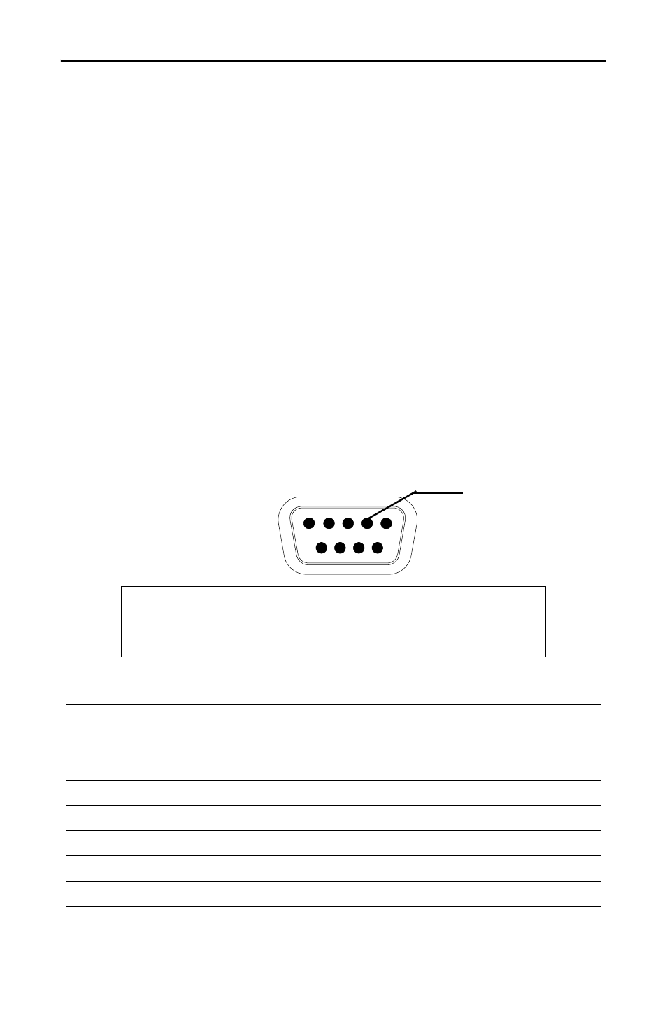
Note:
The chart below Figure 2 identifies the signals on
each pin of the DB-9 connector.
Note:
Above 4VDC, the accuracy spec does not apply.
CAUTION
Pin 4 must be connected to power supply ground,
other grounds can be left open if desired.
Pin
Description
1
Forward Voltage Output, 0 to 5 VDC, 1.0 kohm impedance
2
Ground
3
Reflected Voltage Output, 0 to 5 VDC, 1.0 kohm impedance
4
Power Supply Ground
5
DC Power Input, +11 to +18 VDC, <0.1 A current draw
6
Ground
7
Ground
8
Ground
9
Zero Calibration. DO NOT ground this pin. Leave this pin floating.
1
6
9
5
Pin 4 -
Power Supply
Ground
Figure 2
DB-9
Connector