Checking the insertion loss, Figure 6: checking insertion loss, Figure 5: checking the rejection notch – Bird Technologies 15-69-01 User Manual
Page 9
equal to an insertion loss of 0.6 dB. The relative
index label is used to log specific filter perform-
ance.
.
The insertion loss setting determines the re-
jection response of the cavity and a change will
cause a shift in both the passband and rejection
notch. Higher insertion loss settings will allow
closer passband to notch frequency separations.
Insertion loss can be checked using the IFR
A-7550 spectrum analyzer by following the proce-
dure listed below.
Checking the insertion loss
1. A zero reference must first be established at the
IFR A-7550 before the insertion loss can be
measured. This is accomplished by temporarily
placing a "female union" between the generator
output and analyzer input, see figure 6.
2. Setup the analyzer / generator for the desired
frequency and bandwidth (center of display) and
also a vertical scale of 2 dB/div.
3. Insure that the IFR A-7550 menu's are set as
follows:
DISPLAY - line
MODE - live
FILTER - none
SETUP - 50 ohm/dBm/gen1.
4. The flat line across the screen is the generator's
output with no attenuation, this value will be-
come our reference by selecting the "Mode"
TX RX Systems Inc. Manual 7-9144-1 07/22/96 Page 5
0
200
KHZ / DIV
MHZ
98.00
300
KHZ RES
40
dB
ATT
GEN
dBM
0
10
MSEC
ANALYZER
GENERATE
VARI-NOTCH
FILTER
0
5
10
15
20
2
4
6
8
dB
-2
-4
-6
-8
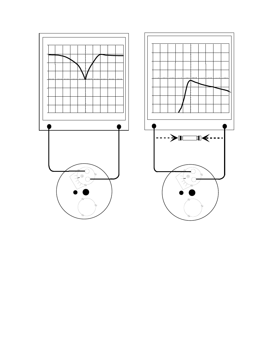
FEMALE UNION
Used to determine 0 dB reference
Figure 6: Checking insertion loss.
0
10
-10
-20
-30
-40
200
KHZ / DIV
MHZ
97.00
300
KHZ RES
dBm
40
dB
ATT
GEN
dBM
0
10
MSEC
ANALYZER
GENERATE
VARI-NOTCH
FILTER
0
5
10
15
20
-50
-60
-70
Figure 5: Checking the rejection notch.