Tuning, Required equipment, Tuning procedure – Bird Technologies 15-69-01 User Manual
Page 6: Passband
TUNING
Required Equipment
The following equipment or it's equivalent is rec-
ommended in order to properly perform the tuning
adjustments for the Vari-Notch filter.
1. IFR A-7550 Spectrum Analyzer with optional
Tracking Generator installed.
2. Eagle Return Loss Bridge (model RLB150N3A).
3. Double shielded coaxial cable test leads
(RG142 B/U or RG223/U).
4. 50 Ohm load, with at least -35 dB return loss
(1.10:1 VSWR).
5. Connector - female union (UG 29-N or UG
914-BNC).
6. Insulated tuning tool (TX RX Systems Inc. part#
95-00-01).
7. 5/32" hex wrench.
Tuning Procedure
Tuning of the filter requires adjustment of the
pass-
band
and the
rejection notch
. The passband is ad-
justed while observing the return loss response and
the rejection notch is adjusted by monitoring the
output of a tracking generator after it passes
through the filter. To insure proper tuning of the
Vari-Notch filter, all adjustments should be per-
formed in the following order:
1. Rough tune the passband.
2. Rough tune the rejection notch.
3. Final tune the passband.
4. Final tune the rejection notch, always the last
adjustment made.
PASSBAND
The peak of the passband will correspond very
closely to the point of minimum reflected energy
from the filter and maximum forward power through
it. A transmitter connected to the filter will
operate
TX RX Systems Inc. Manual 7-9144-1 07/22/96 Page 2
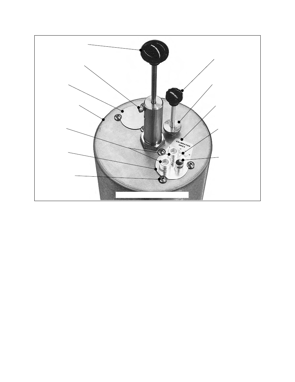
Coarse Tuning Rod
Coarse Tuning Lock
Calibration
Index
Calibration
Loop Plate
Hold Down Screws
Input / Output
Fine Tuning Rod
Cavity Resonator
Fine Tuning Lock
Knurled Thumb Nut
Loop Plate
Assembly
Variable Capacitor
Access Barrel
Ports
Loop Plate
Hole Cover
Mark
10-32 Cap Screw
Figure 2: The Vari-Notch filter.