General description – Bird Technologies 15-69-01 User Manual
Page 5
GENERAL DESCRIPTION
The Vari-Notch® cavity filter is designed to pass a
relatively narrow band of frequencies
(passband)
while simultaneously rejecting a wide band of fre-
quencies
(rejection notch).
A variety of models
are available that cover the range of frequencies
from 30 to 960 MHz. The portion of the frequency
range that each model will tune across is deter-
mined by the cavity's physical length.
Either 6-5/8" or 10" diameter resonator shells may
be used to construct the filters. The difference be-
tween the two sizes determines the filters selectiv-
ity and it's maximum power dissipation. The 10"
diameter filters have a slightly higher selectivity
compared to the 6-5/8" models. Additionally, the
10" filters can safely dissipate up to 40 Watts of RF
Power, while the 6-5/8" filters can dissipate up to
30 Watts. Maximum input power for the 6" and 10"
diameter filter's is listed in table 1.
Two types of Vari-Notch filters are available, low-
pass and highpass. Lowpass filters have the pass-
band below the notch frequency while highpass
filters have the passband above the notch.
The difference between the two types at VHF fre-
quencies is determined by the inductive element
used in the construction of the loop plate assembly.
At UHF frequencies the same loop plate is used for
both low and highpass. The cavity itself remains
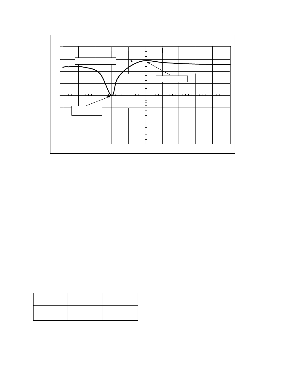
identical for both types. Figure 1 shows the re-
sponse curve of a highpass filter.
There are three adjustable parameters in a Vari-
Notch filter including the passband frequency, the
rejection notch frequency, and insertion loss.
Each of these parameters is labeled on the re-
sponse curve shown in figure 1.
All of the physical components of the filter are la-
beled in figure 2, with the adjustable parts shown in
emboldened italics. Coarse and fine tuning rods
are used to adjust the passband while a variable
capacitor is used to adjust the rejection notch. The
insertion loss is adjusted by rotating the loop plate
assembly.
TX RX Systems Inc. Manual 7-9144-1 07/22/96 Page 1
dBm
REJECTION
NOTCH
INSERTION LOSS
PASSBAND
0
10
-10
-20
-30
-40
-50
-60
-70
200
KHZ/DIV
98.00
MHZ
300
KHZ/RES
10 MSEC
GEN 0 dBM
40 dB ATT
Figure 1: Spectrum Analyzer / Tracking Generator display of the highpass Vari-Notch filter
.
Response curve shown for model # 15-29-01 (88 - 108 MHz)
Insertion loss
6" diameter
power rating
10" diameter
power rating
0.3 dB
449 Watts
599 Watts
0.6 dB
230 Watts
308 Watts
Table 1: Input power ratings