Cavity tuning tip, Rejection notch, Checking the rejection notch – Bird Technologies 15-69-01 User Manual
Page 8: Adjusting the rejection notch, Insertion loss, Figure 4: checking the passband
temperature compensation and detuning of the
cavity.
Cavity Tuning Tip
When tuning a cavity that has been in service for
some time it is not unusual to find the main tuning
rod hard to move in or out. This occurs because
TX RX Systems Inc. uses construction techniques
borrowed from microwave technology that provide
large area contact surfaces on our tuning probes.
These silver plated surfaces actually form a
pressure weld that maintains excellent conductivity.
The pressure weld develops over time and must be
broken in order for the main tuning rod to move.
This is easily accomplished by gently tapping the
tuning rod with a plastic screwdriver handle or
small hammer so it moves into the cavity. The
pressure weld will be broken with no damage to the
cavity.
REJECTION NOTCH
The rejection notch will track with the tuning of the
passband and therefore should be the last adjust-
ment made to the Vari-Notch filter. The rejection
notch is adjusted by changing the amount of ca-
pacitance in the loop plate assembly. The capacitor
is variable and is either an air-plate or a tubular-
piston type depending upon the frequency range of
the filter.
On UHF models (400 MHz and over) the capacitor
access barrel is omitted and a 10-32 screw must
then be removed from the loop plate assembly to
gain access to the piston trimmer under the plate.
The air-plate type has a red mark painted on the
access barrel and one-half of the adjusting screw,
when the red marks line up the maximum capaci-
tance is achieved.
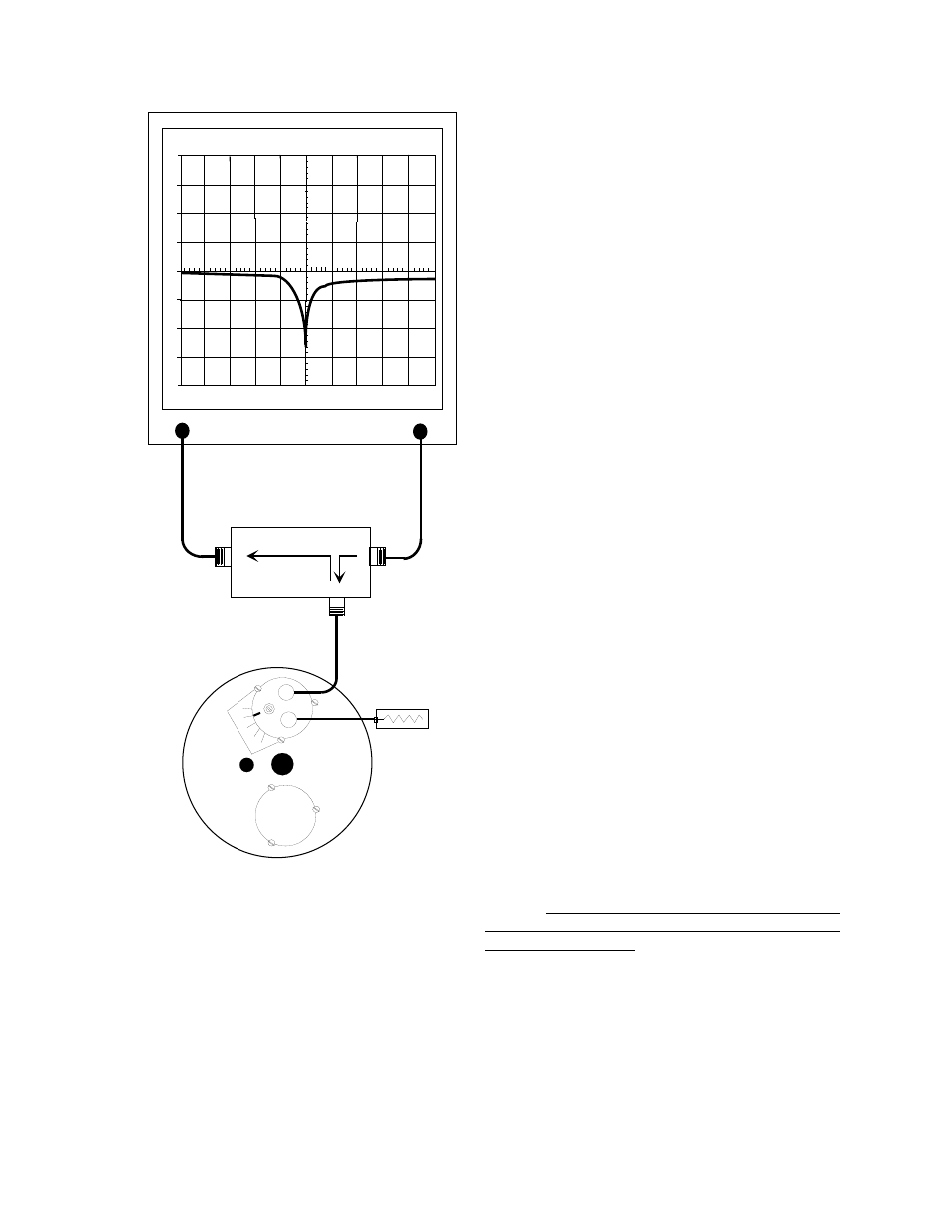
Checking the rejection notch
1. The rejection notch is checked by connecting
the tracking generator to the input of the cavity
filter while the spectrum analyzer is connected
to the output, as illustrated in figure 5.
2. Insure that the IFR A-7550 menu's are set as
follows:
DISPLAY - line
MODE - live
FILTER - none
SETUP - 50 ohm/dBm/gen1.
Adjusting the rejection notch
The notch is adjusted by turning the variable ca-
pacitor. Because of the filters sensitivity to tool
contact, an insulated tuning tool must be used to
make the adjustment.
INSERTION LOSS
Insertion loss is not usually adjusted when re-
tuning the Vari-Notch filter in the field. Insertion
loss is factory set, at which time a relative index
label is attached to the top of the cavity next to the
loop plate and a calibration mark is stamped into
the loop plate itself. The calibration mark is nor-
mally aligned so that the index value of 15 will be
TX RX Systems Inc. Manual 7-9144-1 07/22/96 Page 4
0
10
-10
-20
-30
-40
20
30
40
200
KHZ / DIV
MHZ
98.00
300
KHZ RES
dBm
40
dB
ATT
GEN
dBM
0
10
MSEC
ANALYZER
GENERATE
RLB - 150 BRIDGE
LOAD
REFLECTED
SOURCE
50 OHM LOAD
0
5
10
15
20
VARI-NOTCH
FILTER
Figure 4: Checking the passband.