Adjusting the insertion loss, Multiple cavity vari-notch filters, Converting cavity resonant filters – Bird Technologies 15-69-01 User Manual
Page 10
main menu item and choosing the "Store"
command.
5. Next select the "Display" main menu item and
choose the "Reference" command. This will
cause the stored value to be displayed at the
center of the screen as the 0 dB reference
value.
6. Connect the generator output and analyzer in-
put to the input/output ports of the loop plate
and the amount of insertion loss offered by the
Vari-Notch filter will be displayed on the IFR
A-7550's screen, refer to figure 6.
Adjusting the insertion loss
Adjustments are made by loosening the three
10-32 screws that hold the loop plate into position
and then rotating the plate itself. When the calibra-
tion mark is pointed at the relative index setting of
15 the insertion loss will be 0.6 dB (calibrated by
factory).
Rotating the loop plate assembly and moving the
calibration mark above or below 15 causes the in-
sertion loss to be increased or decreased (above
15 increases the loss while below 15 decreases it)
.
Insertion loss is adjustable across a useable range
of from 0.3 dB to 1.0 dB.
MULTIPLE CAVITY VARI-NOTCH FILTERS
Vari-Notch filters can be ordered in multiple cavity
arrangements of either two or three combined cavi-
ties. In these arrangements, identical filters are
connected in a cascaded fashion with the output of
each filter fed to the input port of the succeeding
filter. The advantage to this arrangement is that the
amount of attenuation provided by each of the fil-
ters is additive. In the case of the rejection notch
frequency, the dual cavity can provide attenuation
of over 60 dB (30 dB for each filter).
Also, the interconnecting cable between the two
filters, when cut to the correct length (odd multiple
of a 1/4
λ
), will provide up to 6 dB of additional at-
tenuation due to a mismatch of impedance be-
tween the cable and the filters. The 6 dB of
mismatch attenuation does not occur at the filters
passband but, only at frequencies where moderate
to high attenuation occurs, such as at the rejection
notch frequency. Because each of the filters in the
multi-cavity arrangement are identical, the pass-
band for the entire arrangement is generally the
same as the passband for the individual filters.
However, each filters individual insertion loss is
also additive. When tuning a multi-cavity arrange-
ment, each filter is tuned individually prior to inter-
connecting them. Then each is fine tuned to peak
the overall response of the multi-cavity
arrangement.
CONVERTING CAVITY RESONANT FILTERS
TX RX Systems Inc. produces four types of cavity
filters, including the Vari-Notch®, Series-Notch®,
Bandpass, and T-Pass®. The cavity resonator shell
along with the coarse and fine tuning controls are
standard subassemblies found in each type of filter
for a specified frequency band. Differences be-
tween the types are determined by the loop plate
assemblies installed in the filter.
The filter's loop plate assembly may be changed in
order to convert the cavity from one type of filter to
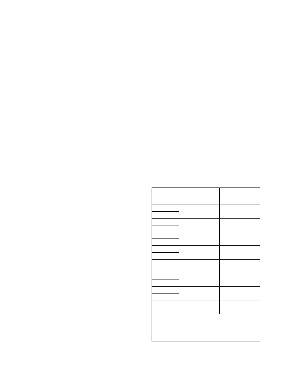
another. Conversion kits can be ordered which
contain all parts required for the conversion. The
available kits are listed by part number in table 2.
Refer to the appropriate TX RX Systems Inc. man-
ual for the specific filter type once the kit is
installed.
TX RX Systems Inc. Manual 7-9144-1 07/22/96 Page 6
Vari- Notch
Filter Part #
Series-Notch
( Lowpass )
Conversion
Kit Part #
Series-Notch
( Highpass )
Conversion
Kit Part #
Bandpass
Conversion
Kit Part #
T-Pass
Conversion
Kit Part #
15-28-01/-11
76-28-04
76-28-05
76-28-01
76-28-07
15-28-05/-25
15-29-01/-11
76-29-04
76-29-05
76-29-01
76-29-07
15-29-05/-25
15-35-01/-11
76-35-04
76-35-05
76-35-01
76-35-07
15-35-05/-25
15-36-01/-11
76-36-05
76-36-06
76-36-01
76-38-01
15-36-05/-25
15-37-01/-11
76-37-05
76-37-06
76-37-01
76-38-01
15-37-05/-25
15-65-01/-11
76-65-04
76-65-05
76-65-01
76-67-01
15-65-05/-25
15-69-01/-11
76-69-04 76-69-05
76-69-01
76-67-01
15-69-05/-25
15-70-01/-11
76-70-04 76-70-05
76-70-01
76-67-01
15-70-05/-25
Note: The last two digits of the filters model number indicate it's
diameter and wavelength as listed below;
1.) Last digit of "01" indicates 6-5/8" diameter and 1/4
λ
.
2.) Last digit of "11" indicates 6-5/8" diameter and 3/4
λ
.
3.) Last digit of "05" indicates 10" diameter and 1/4
λ
.
4.) Last digit of "25" indicates 10" diameter and 3/4
λ
.
Table 2: Conversion kit part numbers.