Checking the passband, Adjusting the passband, Figure 3: setting the return loss reference – Bird Technologies 15-69-01 User Manual
Page 7
best when the reflected energy is lowest, therefore
the return loss response will be used to set the
passband. The passband can be checked and ad-
justed using the following procedure.
Checking the passband
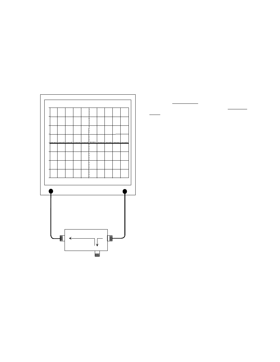
1. A zero reference for return loss must be estab-
lished at the IFR A-7550 prior to checking the
passband frequency, this is done by connecting
the return loss bridge to the analyzer / genera-
tor as shown in figure 3.
2. Set-up the analyzer / generator for the desired
frequency (center of display) and for a vertical
scale of 10 dB/div.
3. Do not connect the return loss bridge to the
cavity, leave the "load" port on the bridge open.
This will supply the maximum amount of re-
flected energy to the analyzer input.
4. Insure that the IFR A-7550 menu's are set as
follows:
DISPLAY - line
MODE - live
FILTER - none
SETUP - 50 ohm/dBm/gen1.
5. The flat line across the screen is the return loss
curve. Select the "Mode" main menu item and
then choose the "Store " command.
6 Next select the "Display" main menu item and
choose the "Reference" command. This will
cause the stored value to be displayed at the
center of the screen as the 0 dB reference
value.
7. Connect the "load" port on the RLB to the input
of the loop plate, make sure the output of the
loop plate is connected to a 50 ohm load, refer
to figure 4. The display will now present the re-
turn loss curve for the Vari-Notch filter being
measured. The passband is that frequency
range over which the return loss is 15 dB or
greater.
Adjusting the passband
Set the fine tuning knob at it's mid-point. Adjust the
passband by setting the peak (maximum negative
value) of the return loss curve at the desired pass-
band frequency (should be the center-vertical
graticule line on the IFR A-7550's display). Refer to
figure 4.
The resonant frequency is adjusted by using the
coarse tuning rod, which is a sliding adjustment (in-
var rod) that rapidly tunes the response curve
across the frequency range of the filter. Resonant
frequency is increased by pulling the rod out of the
cavity and is decreased by pushing the rod into the
cavity. Additionally, the fine tuning rod, also a slid-
ing adjustment (silver-plated-brass rod ), allows a
more precise setting of the frequency after the
coarse adjustment is made. The frequency is in-
creased by pushing the fine tuning rod in and is de-
creased by pulling it out; the exact opposite of the
coarse tuning rod.
Once the desired response is obtained using the
coarse and fine tuning rods, they are "locked" in
place. The coarse rod is secured by tightening the
10-32 cap screw and the fine tuning rod is held in
place by tightening the knurled thumb nut. Failure
to lock the tuning rods will cause a loss of
TX RX Systems Inc. Manual 7-9144-1 07/22/96 Page 3
0
10
-10
-20
-30
-40
20
30
40
200
KHZ / DIV
MHZ
98.00
300
KHZ RES
dBm
40
dB
ATT
GEN
dBM
0
10
MSEC
ANALYZER
GENERATE
RLB - 150 BRIDGE
LOAD
REFLECTED
SOURCE
Figure 3: Setting the return loss reference.