Figure 5 coupling connections, Wattcher rfmonitor/alarm, Elements – Bird Technologies 3128A User Manual
Page 22: Wattcher rfmonitor/alarm elements
10
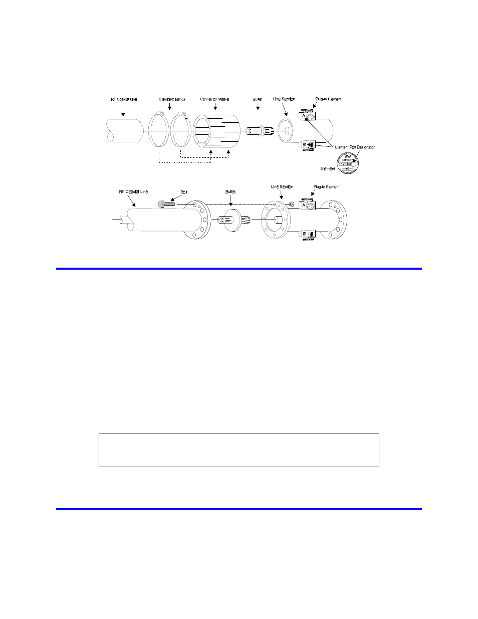
Figure 5 Coupling Connections
Wattcher RFMonitor/Alarm
The Wattcher is designed to mount in an EIA standard 19" relay rack. Wire lengths are not critical, the unit may be
installed where convenient for monitoring and operation. The following connections and switch settings should be
made before installation. See “Operating Instructions” on page 11 for descriptions of various modes.
•
Auxiliary DC
•
Remote reset
•
Interlock
•
Alarm enable/disable mode selected
•
Fail-safe / non fail-safe mode selected
•
Forward and reflected power sensor cables
•
Forward power sensor cable from port A of the line section
•
Reflected power sensor cable from port B of the line section
Note: AC line voltage selector switch is in the appropriate position. Voltage visible in the switch window is
selected voltage.
•
AC power cable connected
Elements
The element port designator is stamped on the line section ports and after the serial numbers on the elements. Be
sure to match these designators to achieve stated accuracy. Refer to Figure 5.
CAUTION
Be sure voltage selector switch is in the appropriate position before applying AC power.
Failure to do so will damage the unit.